
Polishing jig for rolling mill backup roll bearing

a technology of rolling mill and rolling mill, which is applied in the direction of grinding machine components, manufacturing tools, mechanical equipment, etc., can solve the problems of low efficiency of conventional polishing jig, affecting the thickness of sheet material being rolled, and requiring a large number of polishing back bearings, so as to enhance the versatility of polishing jig and increase efficiency. efficiency, the effect of increasing efficiency

Inactive Publication Date: 2004-10-07
KOYO SEIKO CO LTD
View PDF4 Cites 1 Cited by
  • Summary
  • Abstract
  • Description
  • Claims
  • Application Information

AI Technical Summary

Benefits of technology

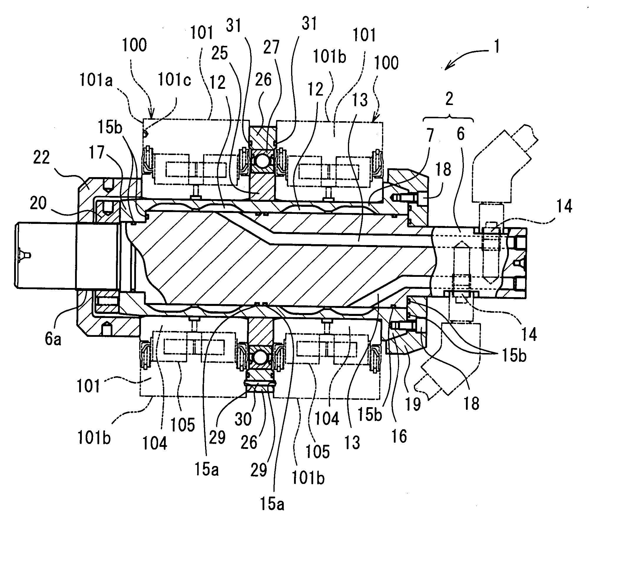
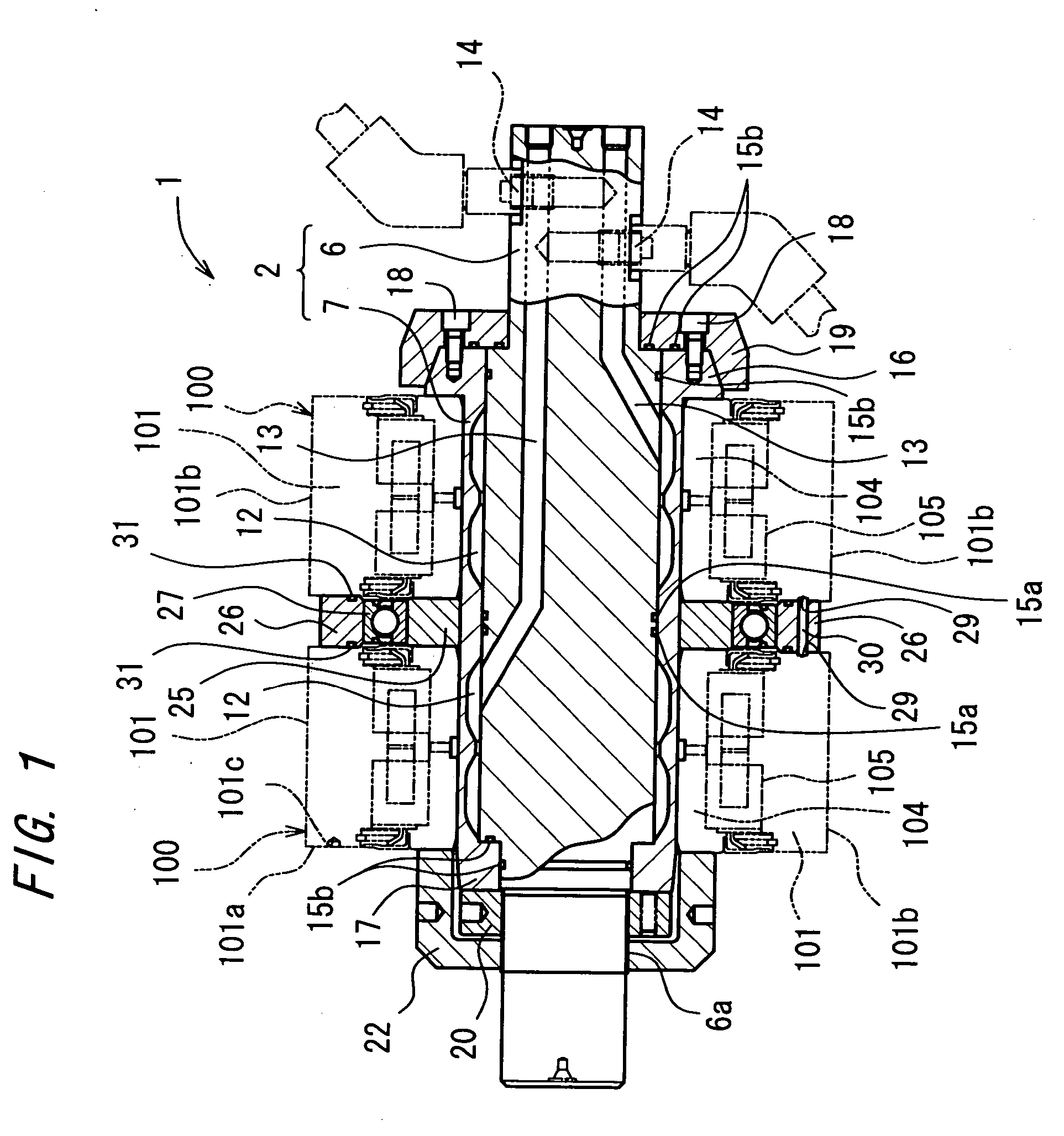
[0009] According to the first aspect of the present invention, the plural bearings can be fitted on the shaft member as axially arranged thereon so that the individual inner rings can be fixed thereon. Furthermore, since the plural pressure-oil chambers are formed in correspondence to the individual bearings, it is possible to apply a radially-outward expansion force to the corresponding inner rings of the individual bearings. Hence, outside diameter surfaces of the plural bearings can be polished with high accuracy and efficiency.
[0011] According to the second aspect of the present invention, the plurality of individually independent pressure-oil chambers and oil paths are formed in correspondence to the plural bearings and hence, outside diameter surfaces of the plural bearings can be polished with high accuracy and efficiency. Furthermore, since the individual pressure-oil chambers are adapted for discrete adjustment of oil pressure, the amount of protrusion of the shaft member may be adjusted according to individually varied inside diameters of the inner rings and internal radial clearances of the bearings. Thus, the individual bearings can be polished under optimum conditions.
[0013] According to the third aspect of the present invention, the plural bearings can be fixed so as to be efficiently finished. In addition, the interconnection portion interconnects the individual outer ring, thereby facilitating the synchronous rotation of the outer rings of the plural bearings.
[0014] In a fourth aspect of the present invention, the polishing jig of the arrangement of the third aspect hereof further comprises an inner-ring spacer interposed between the inner rings; and an outer-ring spacer interposed between the outer rings as allowed to rotate relative to the inner-ring spacer via a spacer bearing. According to the fourth aspect of the present invention, it is possible to increase the rotational accuracies of the individual bearings, and to ensure a polishing accuracy equal to that of polishing bearings one by one.
[0016] According to the fifth aspect of the present invention, when the outer ring is retained by the outer-ring retaining portion, the torque from the torque generating machine such as a polishing machine can be transmitted to the outer ring via the torque transmission portion provided at the outer-ring retaining portion. This permits even an outer ring free from an engagement hole to be rotated without forming the engagement hole thereat, thus contributing to the increased efficiency. In addition, the versatility of the polishing jig is enhanced because the polishing jig is capable of rotating the outer ring regardless of the presence of the engagement hole.
[0017] The above-mentioned outer-ring retaining portion may preferably serve to fix the outer ring axially of the shaft member. In this case, the outer-ring retaining portion is capable of axially fix even the outer ring of a bearing which cannot be axially positioned without the aid of a thrust washer. Thus, the versatility of the polishing jig is even further enhanced.

Problems solved by technology

A bearing (backing bearing) for use in back-up roll of rolling mill is in contact with a roll at its outer ring as a rotational ring and hence, the outer ring suffers fast deformation of its outside diameter surface or slip scars thereon, thus adversely affecting the thickness of a sheet material being rolled.
However, a single conventional polishing jig can polish only one backing bearing, thus requiring much time to polish a large number of backing bearings.
As a consequence, the conventional polishing jig suffers low efficiency.
In a case where a bearing with no engagement hole formed at the end face is to be re-polished, there occurs a need to form the engagement hole, which results in low efficiency.

Method used


Image

  • Polishing jig for rolling mill backup roll bearing
  • Polishing jig for rolling mill backup roll bearing
  • Polishing jig for rolling mill backup roll bearing

Examples


first embodiment

[0021] FIG. 1 shows a polishing jig 1 according to the present invention. The polishing jig 1 is used for re-polishing outside diameter surfaces of outer rings 101b of a plural number of (specifically, two) bearings (backing bearings) 100 for back-up roll of rolling mill, the bearings 100 staying undisassembled or maintained as bearing assemblies when subjected to the re-polishing process.

[0022] It is noted here that the backing bearing 100 as a polishing subject includes an outer ring 101, an inner ring 104 and rollers 105. A side face 101a of the outer ring 101 is formed with an engagement hole 101c to be engaged with a carrier projected from a work head of a polishing machine such as a cylindrical grinder. The outer ring 101 is rotated in unison with the work head by way of engagement between the carrier and the engagement hole 101c.

[0023] The polishing jig 1 includes a shaft member 2 on which the inner ring 104 of the bearing assembly 100 is fitted. The shaft member 2 includes a...

second embodiment

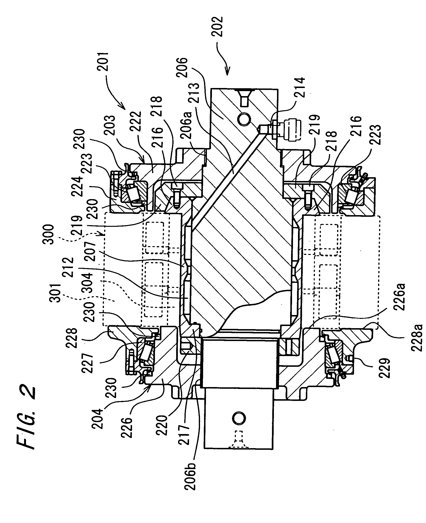
[0035] FIG. 2 illustrates a polishing jig 201 according to the present invention. The polishing jig 201 is favorably used for re-polishing an outside diameter surface 301b of an outer ring of a bearing 300 for use in back-up roll of rolling mill (backing bearing) as shown in FIG. 3 without disassembling the bearing or maintaining the bearing assembly as it is. The polishing jig 201 is particularly suited for a bearing free from an engagement hole to engageably receive a carrier of a work head.

[0036] This bearing 300 differs from the bearing finished by the prior art disclosed in Japanese Examined Patent Publication No. 63-41704. That is, this bearing 300 is not formed with ajaw at an inside diameter portion of its outer ring. In the case of the bearing 300 wherein an outer ring 301 is free from the jaw as shown in FIG. 3, a thrust washer 303 formed from a resin material is interposed between a back-up saddle 302 and an end face 301a of the outer ring 301 for the purpose of axially f...


PUM

PropertyMeasurementUnit
Pressureaaaaaaaaaa
Diameteraaaaaaaaaa
Efficiencyaaaaaaaaaa

Abstract

A polishing jig of a hydraulic integral system is improved to increase efficiency. A polishing jig 1 for bearing for use in back-up roll of rolling mill including a shaft member 2 on which an inner ring 104 of a bearing 100 for use in back-up roll of rolling mill is fitted; and a pressure-oil chamber 12 operative in association with the feeding of a pressure oil into the shaft member 2 to protrude an outer circumferential part of the shaft member 2 radially outwardly, the polishing jig includes an inner-ring fixing portion 16 for axially fixing individual inner rings 104 of a plurality of the bearings 100 fitted on the shaft member 2 as axially arranged, wherein a plurality of the pressure-oil chambers 12 are formed internally of the shaft member 2 in correspondence to the plural bearings 100 fixed on the shaft member 2.

Description

[0001] The present invention relates to a polishing jig for bearing for use in back-up roll of rolling mill.[0002] A bearing (backing bearing) for use in back-up roll of rolling mill is in contact with a roll at its outer ring as a rotational ring and hence, the outer ring suffers fast deformation of its outside diameter surface or slip scars thereon, thus adversely affecting the thickness of a sheet material being rolled. Accordingly, the bearing requires frequent re-polishing of the outside diameter surface of its outer ring.[0003] As a polishing jig for the outside diameter surface of the outer ring of the bearing for use in back-up roll of rolling mill, there has conventionally been known one disclosed in Japanese Examined Patent Publication No. 63-41704 (hereinafter, referred to as a prior art).[0004] The polishing jig (re-polishing machine) of the prior art performs high accuracy polishing of the outside diameter surface of the outer ring by rotating only the outer ring via an...

Claims


Application Information

Patent Timeline
IPC IPC(8): B21B28/02B21B28/04B21B31/07B24B5/37B24B41/06
CPCB21B28/02B21B31/07B24B5/37B24B41/06F16C33/64F16C13/02F16C2322/12
Inventor HIGUCHI, KUNIO
Owner KOYO SEIKO CO LTD
Learn More