Method to determine tdc in an internal combustion engine

a technology of internal combustion engine and tdc, which is applied in the direction of electric control, ignition automatic control, instruments, etc., can solve the problems of negative influence on the working life of the combustion engine, difficult measurement, and calculation of work output, so as to achieve effective management of the engine under operation, effective development of new ideas, and determination more accurately

a technology of internal combustion engine and tdc, which is applied in the direction of electric control, ignition automatic control, instruments, etc., can solve the problems of negative influence on the working life of the combustion engine, difficult measurement, and calculation of work output, so as to achieve effective management of the engine under operation, effective development of new ideas, and determination more accurately

US20040236496A1Inactive Publication Date: 2004-11-25ABB (SCHWEIZ) AG

Image

  • Method to determine tdc in an internal combustion engine
  • Method to determine tdc in an internal combustion engine
  • Method to determine tdc in an internal combustion engine

Examples


Embodiment Construction

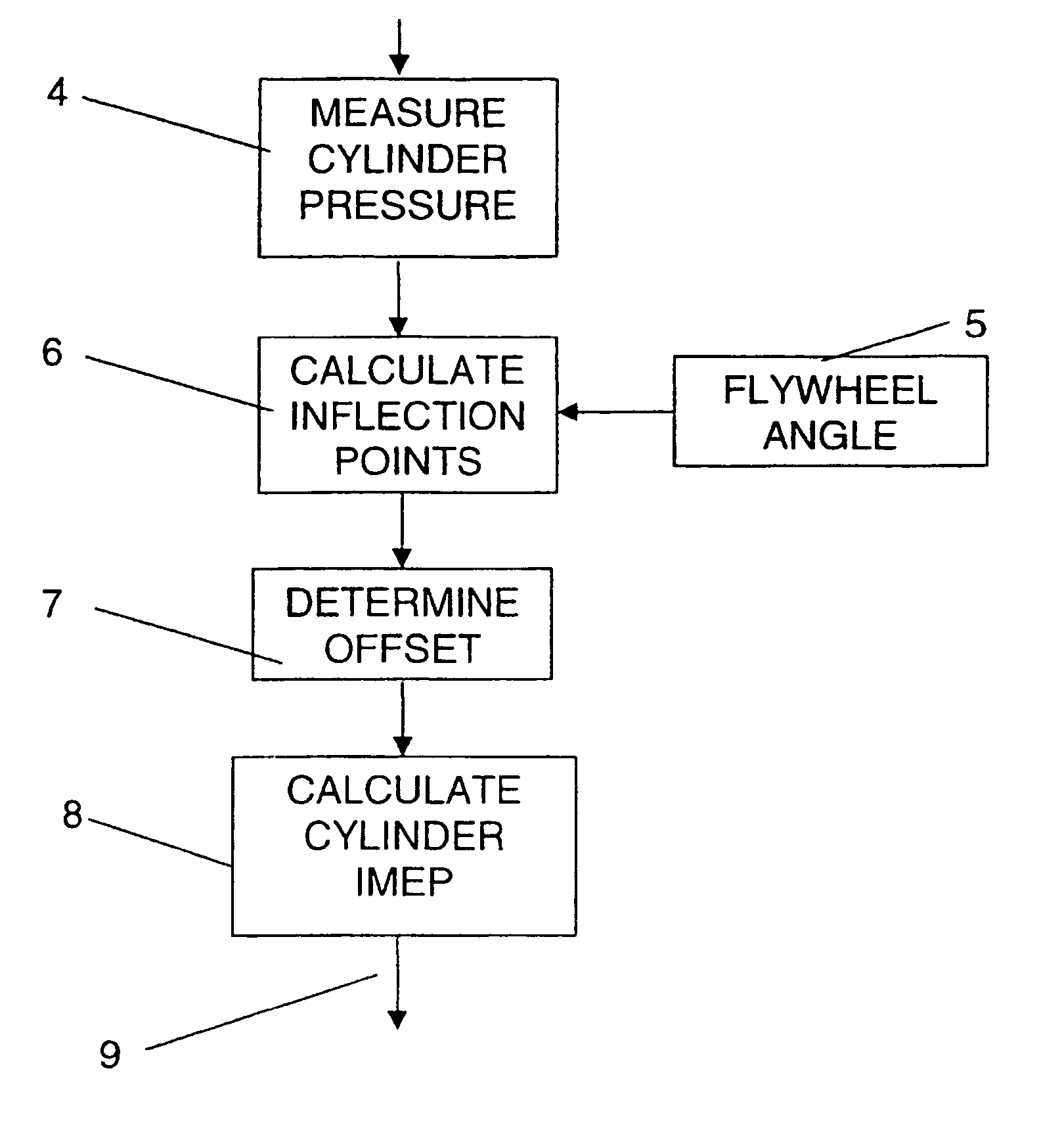
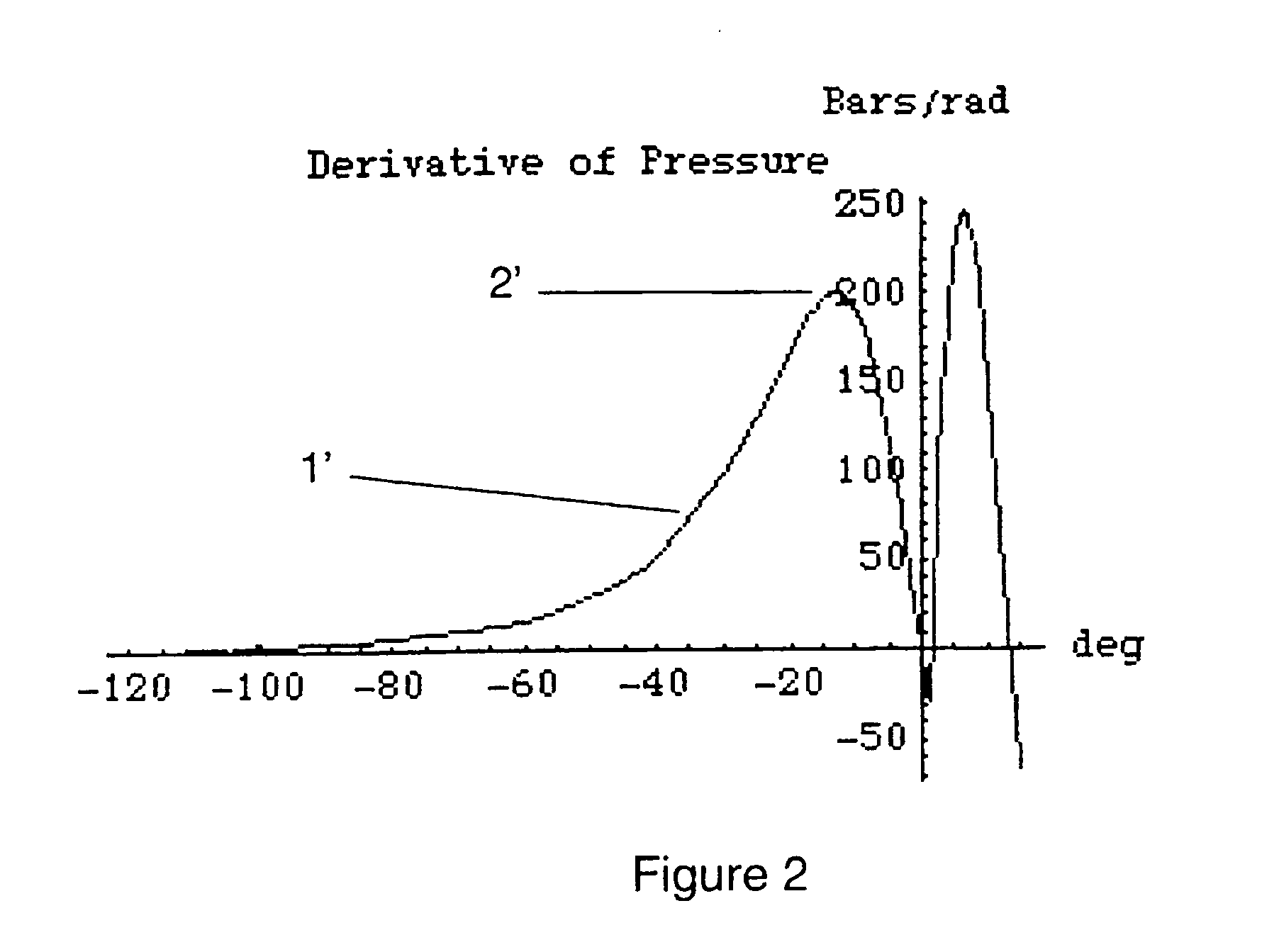
[0027] In order to determine a Top Dead Centre position of the piston in a cylinder the present invention comprises a method for determining a point of inflection in a curve dependent on a measurement of cylinder pressure related to crank angle. That is, the point in the pressure curve at which a derivative of the pressure curve in relation to crank angle is at a maximum or equivalent, and where a second derivative of the pressure curve is equal to zero.

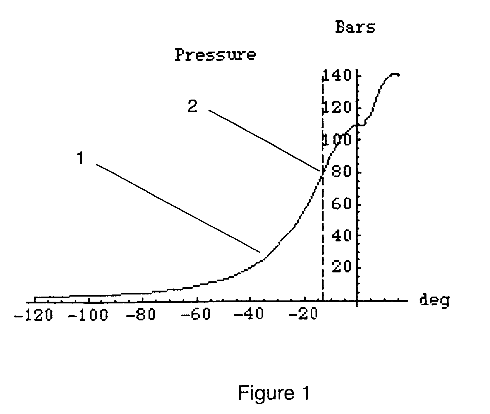
[0028] FIG. 1 shows a schematic graph of a curve 1 for measured cylinder pressure on the y-axis plotted against crank angle in degrees on the x-axis. A first point of inflection 2 may be seen at about -13.degree. on the curve.

[0029] The position of that point .alpha. (in radians) may be determined theoretically with the help of a fairly complicated formula as follows: 1 = - 4 ( 1 + )( 1 + 2 ( - 0.0217 ) )( r c - 1 )+4 3( - 1 - 3+ 32)( 5 + 4 ( - 0.0217 )) ( 1 + ) 2 ( 1 + 2 ( -0.0217 )) 3 ( r c - 1 ) 2

[0030] where

[0031] .lambda.=Relati...


PUM


Abstract

A method and apparatus for accurately determining TTX: in a cylinder of an internal combustion engine. Gas pressure is measured in the cylinder relative to crank angle, giving rise to a curve of gas pressure with crank angle. An offset is found by first computing the angular position of an inflexion point of the compression pressure curve measured as a function of the crank angle, and then computing the offset as the difference between the angular position of a piston in the cylinder and a theoretical value for said angular position of the piston dependent on a known or measured flywheel angle. The value of TDC corrected by the offset is then used to calculate a value of work output such as the indicated Mean Effective Pressure (IMEP) which may be used for diagnostic and / or control purposes.

Description

TECHNICAL AREA[0001] The present invention concerns the technical area of methods to calculate variables useful in performing diagnostics and control of a combustion engine, such as the Indicated Mean Effective Pressure (IMEP), and other variables which require that the crank angle of the piston in the cylinder is accurately known. In particular the invention concerns a method to determine accurately when a piston in a cylinder of an internal combustion engine is at top dead centre (TDC).TECHNICAL BACKGROUND[0002] Many methods exist for controlling operation of a combustion engine. In particular, measurements of pressure from one or more cylinders of an engine are commonly used as a basis for engine performance measurement, monitoring and for control of an engine.[0003] One area of use for continually measuring pressure sensors is in very large combustion engines which are operated at relatively low revolutions per minute. Such motors are used for example as ships engines and as sta...

Claims


Application Information

Patent Timeline
25 Nov 2004
Publication
US20040236496A1
IPC
F02D45/00; F02D13/02; F02D35/00; F02D35/02; F02D41/40; F02P5/15; G01M15/06
CPC
F02D13/02; F02D35/0007; F02D35/023; G01M15/06; F02D41/401; F02D2200/0402; F02P5/1504; F02D41/009
Inventors
SOBEL, JARL R.