

Binderless storage phosphor screen
- Summary
- Abstract
- Description
- Claims
- Application Information
AI Technical Summary
Benefits of technology
Problems solved by technology
Method used
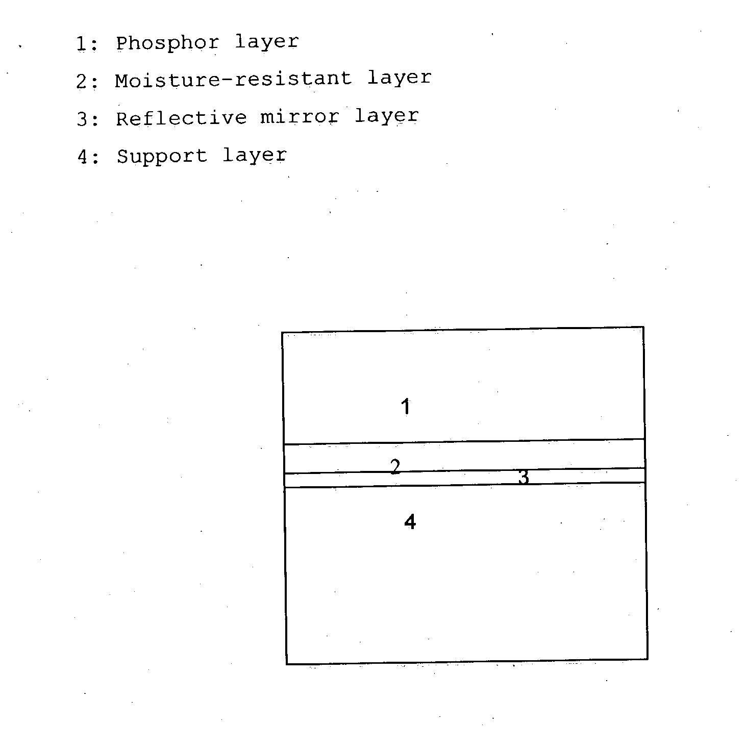
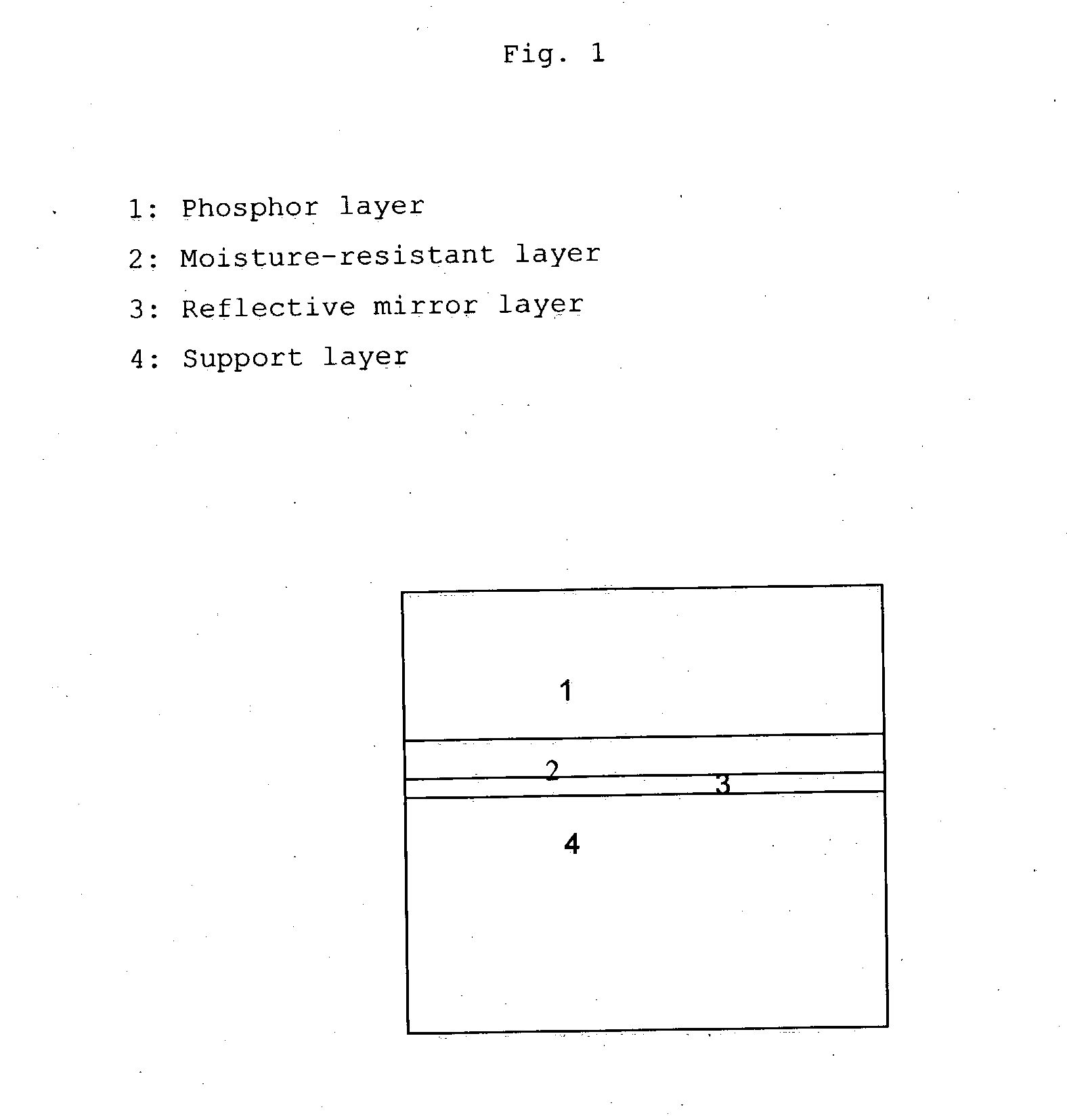
Image

Examples
Embodiment Construction
[0118] A. Preparation of the Vapor Deposited Screens:
[0119] The only differences in the preparation method were related, apart for the choice of the crucible temperature (850.degree. C.), with the crucible design, in that an improved refractory (tantalum) crucible was used wherein a more homogeneous heating provoked a more homogeneous melting and composition of the vapor stream after evaporation.
[0120] Different screens were produced with differing substrates. Before the start of the evaporation, the chamber was evacuated to a pressure of 4.10.sup.-5 mbar.
[0121] A first screen (S-D) was made with an Al substrate. Because of its composition and surface roughness the Al substrate was dull and did not reflect in a mirrorlike way.
[0122] A second screen was made on an a-C substrate on which an Al mirror was applied by vapor deposition (S-M). The substrate had a clear mirrorlike reflection, because of the surface smoothness and because of the pureness of the aluminum.
[0123] For both scree...
PUM
 Abstract
Description
Claims
Application Information