Method for operating an internal combustion engine

Inactive Publication Date: 2005-01-06
ROBERT BOSCH GMBH
View PDF24 Cites 42 Cited by
  • Summary
  • Abstract
  • Description
  • Claims
  • Application Information

AI Technical Summary

Benefits of technology

[0005] In contrast, with the exemplary method of the present invention, the electrically operated air compressor used in the operation of the internal combustion engine is activated during a starting process of the internal combustion engine. In this way, the air-mass flow supplied to the engine is even further in

Problems solved by technology

This leads to a rise in the exhaust-gas enthalpy flow, a

Method used


Image

  • Method for operating an internal combustion engine
  • Method for operating an internal combustion engine
  • Method for operating an internal combustion engine

Examples


Embodiment Construction

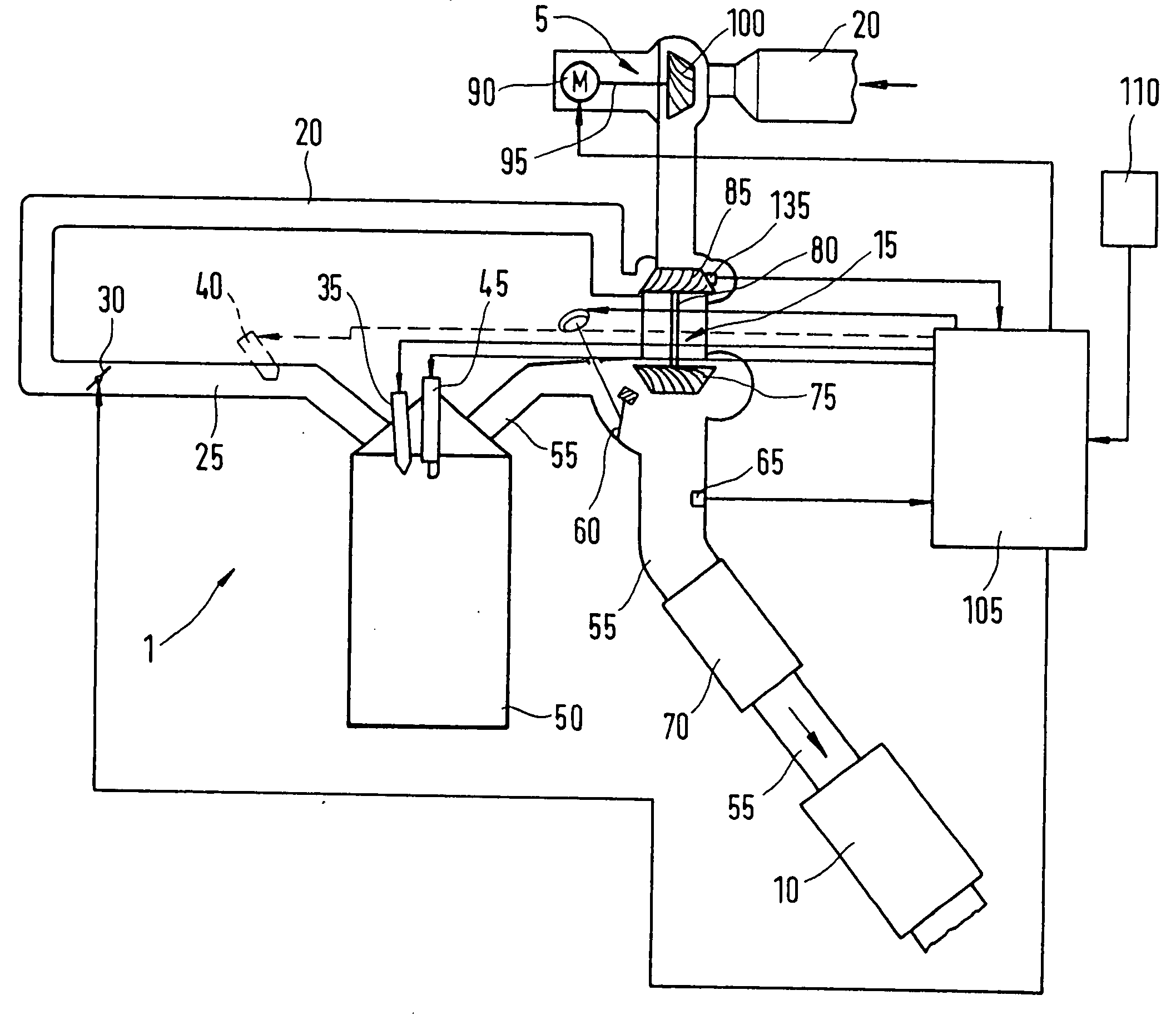
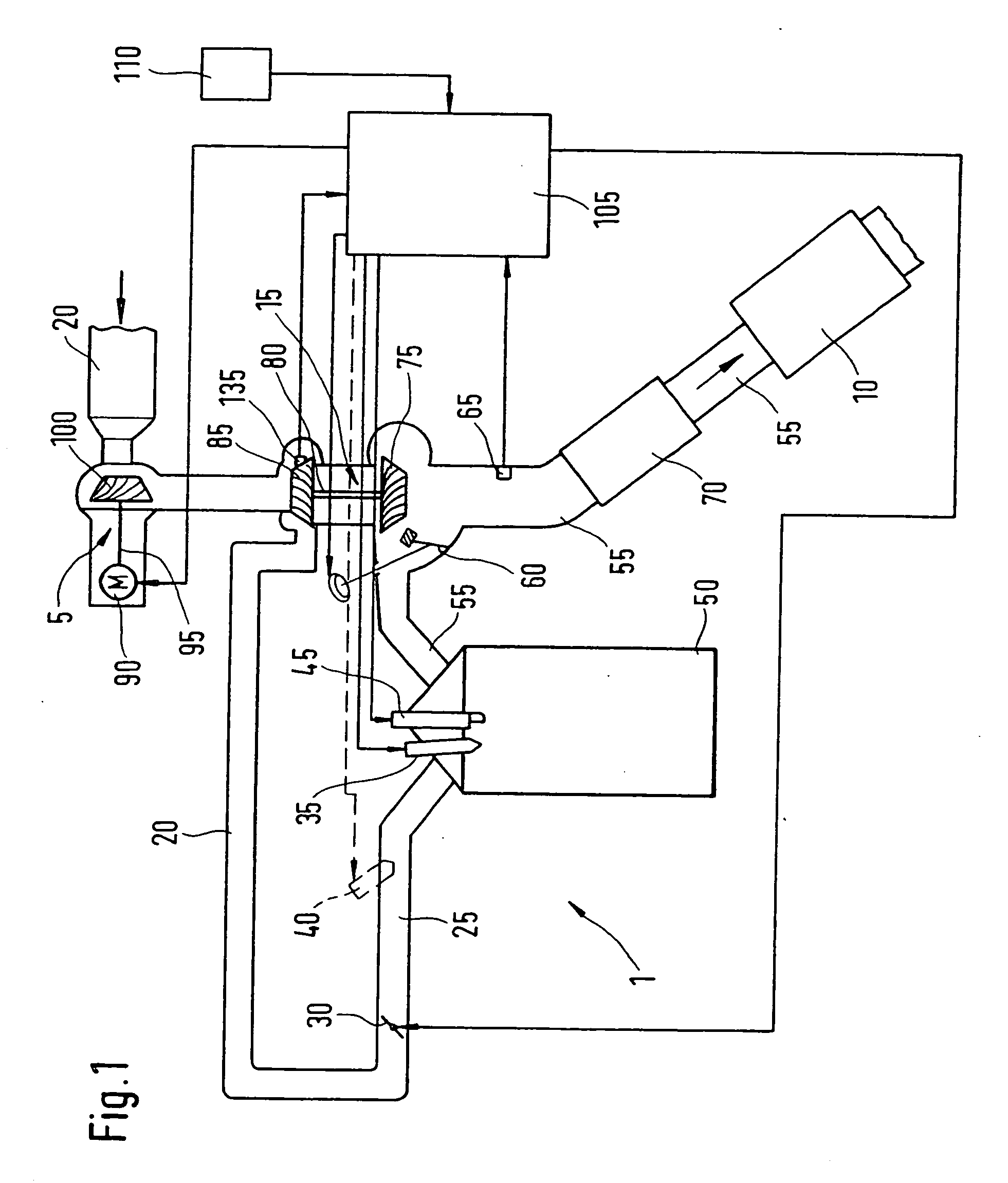
[0015] In FIG. 1, numeral 1 designates an internal combustion engine, for example, of a motor vehicle. Internal combustion engine 1 includes a combustion engine 50 which, for example, may take the form of a gasoline engine. Fresh air is supplied in the arrow direction via an air feed 20 to a combustion chamber (not shown in FIG. 1 for reasons of clarity) of combustion engine 50. Positioned in air feed 20 is a first air compressor 100 that is electrically driven by an electric motor 90 via a first shaft 95. In this example, first air compressor 100, first shaft 95 and electric motor 90 form an electric air compressor 5, also designated in the following as electric auxiliary air compressor.

[0016] In addition to electric auxiliary air compressor 5, as shown in FIG. 1, a second air compressor 85 may be positioned in air feed 20 in series with first air compressor 100. Second air compressor 85 is merely optionally provided. It is driven by a turbine 75 in an exhaust branch 55 of combust...


PUM


Abstract

A method for operating an internal combustion engine using an electrically operated air compressor that allows for heating up an exhaust-gas treatment device more rapidly. The electrically operated air compressor is activated during a starting process of the internal combustion engine.

Description

FIELD OF THE INVENTION [0001] The present invention relates to a method for operating an internal combustion engine. BACKGROUND INFORMATION [0002] An internal combustion engine may be operated using an electrically operated air compressor. [0003] Also, various methods may be used to rapidly heat up a catalytic-converter system to its operating temperature, in order to reduce the emission of pollutants after the start when using a gasoline engine. A distinction may be made between methods which “primarily” provide chemical energy, e.g. in the form of a rich exhaust gas in combination with secondary air, and methods which increase the sensible heat in the exhaust gas, for example, by retarding the ignition angle. [0004] In the case of retarding the ignition angle, which corresponds to a deterioration in the mechanical efficiency of the engine, the air-mass flow supplied to the engine is increased in conjunction with an adjustment of the fuel-mass flow, and the ignition angle is adjust...

Claims


Application Information

Patent Timeline
IPC IPC(8): F02B33/00F01N3/20F01N3/24F01N13/02F02B23/10F02B37/04F02B37/11F02B37/14F02B37/18F02B39/10F02B75/12F02D23/00F02D23/02F02D41/00F02D41/02F02D41/06F02D41/34F02N9/04
CPCF01N3/2006F01N13/009F02B23/101F02B37/11F02B37/14F02B37/18F02B39/10F02B2075/125F02B2275/16F02D23/02F02D41/0007F02D41/062F02N9/04Y02T10/123Y02T10/144Y02T10/26F01N13/0093F01N2430/00F02N19/00Y02T10/12
Inventor NAU, MICHAELKUFFERATH, ANDREASLANDENFELD, TILO
Owner ROBERT BOSCH GMBH
Why Eureka
Try Eureka