Flow sensor having improved operational performance

a flow sensor and operational performance technology, applied in the direction of electrical control, instruments, measurement devices, etc., can solve the problems of falsified output signals provided by flow sensors, inability to detect, and negative effect of output signal precision of bridge circuits

Inactive Publication Date: 2005-01-06
ROBERT BOSCH GMBH
View PDF2 Cites 15 Cited by
  • Summary
  • Abstract
  • Description
  • Claims
  • Application Information

AI Technical Summary

Benefits of technology

[0007] Moreover, it has shown to be advantageous if the temperature of the heating resistor element is controlled by a differential amplifier, the already mentioned bridge circuit providing the voltage differential to be amplified.

Problems solved by technology

Due to environmental influences and the drift of the individual resistor elements, the operational performance of the bridge circuit changes over the course of time, which has a negative effect on the precision of the output signal of the bridge circuit.
As a result, the output signals provided by the flow sensor are falsified as well, which the downstream evaluation circuits are unable to detect.

Method used


Image

  • Flow sensor having improved operational performance
  • Flow sensor having improved operational performance

Examples


Embodiment Construction

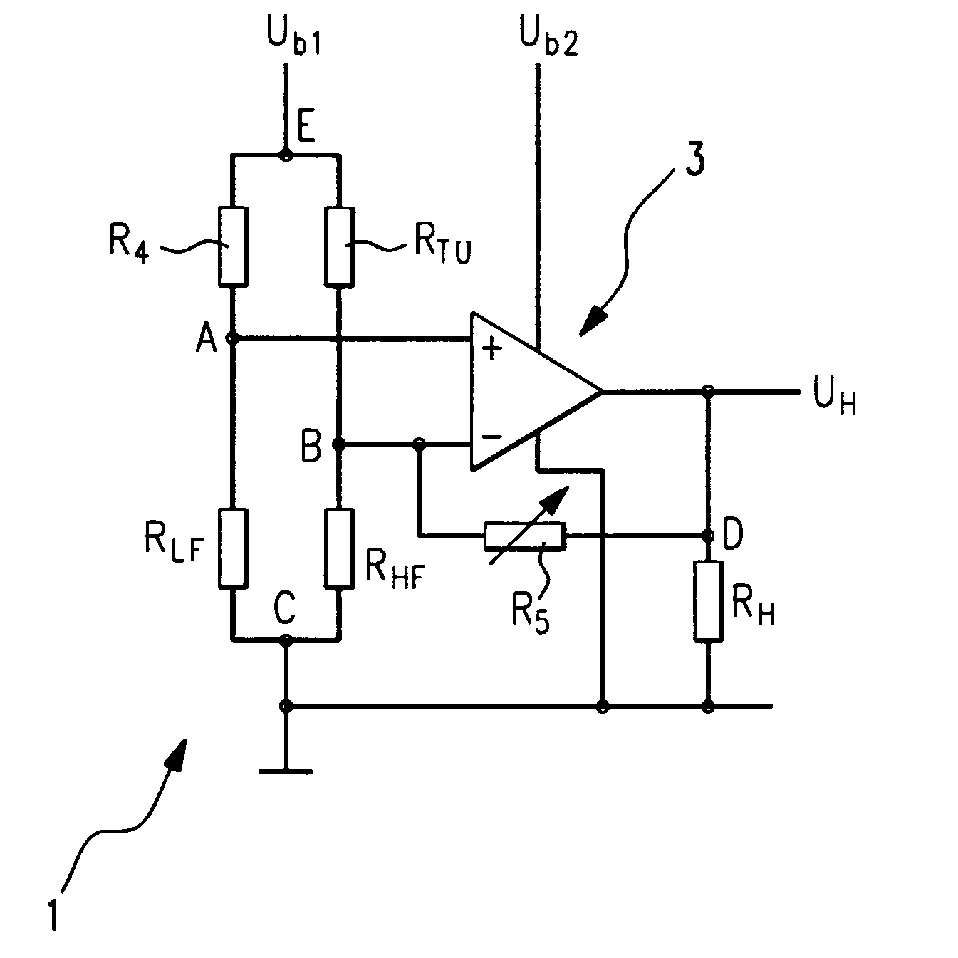
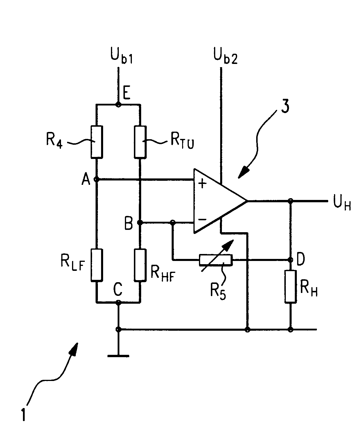
[0011] The FIGURE shows the circuit diagram of a flow sensor according to the present invention. The flow sensor is made up of a measuring element having a bridge circuit 1 and a heating resistor element RH as well as a differential amplifier 3. Bridge circuit 1 is made up of four bridge resistor elements RLF, RHF, RT0 and R4. Bridge-resistor element RHF is a resistance temperature sensor, which is arranged on a chip (not shown) in the immediate vicinity of heating resistor element RH. The temperature of heating resistor element RH is determined via the temperature-dependent resistance of bridge resistor element RHF.

[0012] Bridge resistor element RLF is likewise a resistance temperature sensor arranged on the chip (not shown) at a distance from heating resistor element RH. Using bridge resistor element RLF, temperature Tamb of the ambient air is measured before it reaches heating resistor element RH and is heated by it. The difference in the resistances of bridge resistor elements ...


PUM


Abstract

A flow sensor in which all bridge resistor elements of a bridge circuit are arranged on a chip together with a heating resistor element, so that the drift of the bridge resistor elements will then have only a very slight effect on the output signal of the bridge circuit, which may be picked off at the electrical connections.

Description

BACKGROUND INFORMATION [0001] The present invention relates to a so-called hot-film air-mass sensor as it is used to determine the air mass drawn in by an internal combustion engine, for example. In these hot-film air mass sensors, which are called flow sensors in the following, one or a plurality of heating resistor elements is / are heated to a predefined temperature by applying an electrical voltage. As a rule, the temperature of the heating resistor element(s) exceeds the ambient temperature by a fixed amount. [0002] Two temperature sensors are required to control the temperature of the heating resistor element. A first temperature sensor is arranged in the immediate vicinity of the heating resistor element and measures the temperature of the heating resistor element, while a second temperature sensor measures the ambient temperature. Both temperature sensors are usually implemented as resistance-temperature sensors. The temperature difference between the ambient temperature and t...

Claims


Application Information

Patent Timeline
Patent Type & Authority Applications(United States)
IPC IPC(8): F02D35/00F02D45/00G01F1/684G01F1/699
CPCG01F1/699G01F1/6845
Inventor KONZELMANN, UWELANG, TOBIAS
Owner ROBERT BOSCH GMBH
Why Eureka
Try Eureka