Variable valve timing controller for an engine

a timing controller and variable valve technology, applied in the direction of electric control, ignition automatic control, machines/engines, etc., can solve the problem of unstable combustion within the engine cylinder

Active Publication Date: 2005-01-06
MITSUBISHI MOTORS CORP
View PDF6 Cites 12 Cited by
  • Summary
  • Abstract
  • Description
  • Claims
  • Application Information

AI Technical Summary

Benefits of technology

[0012] The present invention has been made in view of the problems described above. Accordingly, it is the primary object of the prese

Problems solved by technology

However, the retardation of ignition timing causes c

Method used


Image

  • Variable valve timing controller for an engine
  • Variable valve timing controller for an engine
  • Variable valve timing controller for an engine

Examples


Embodiment Construction

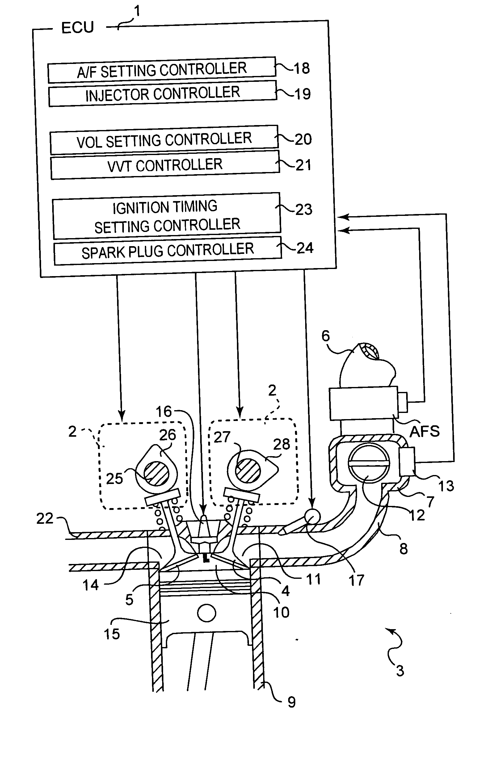
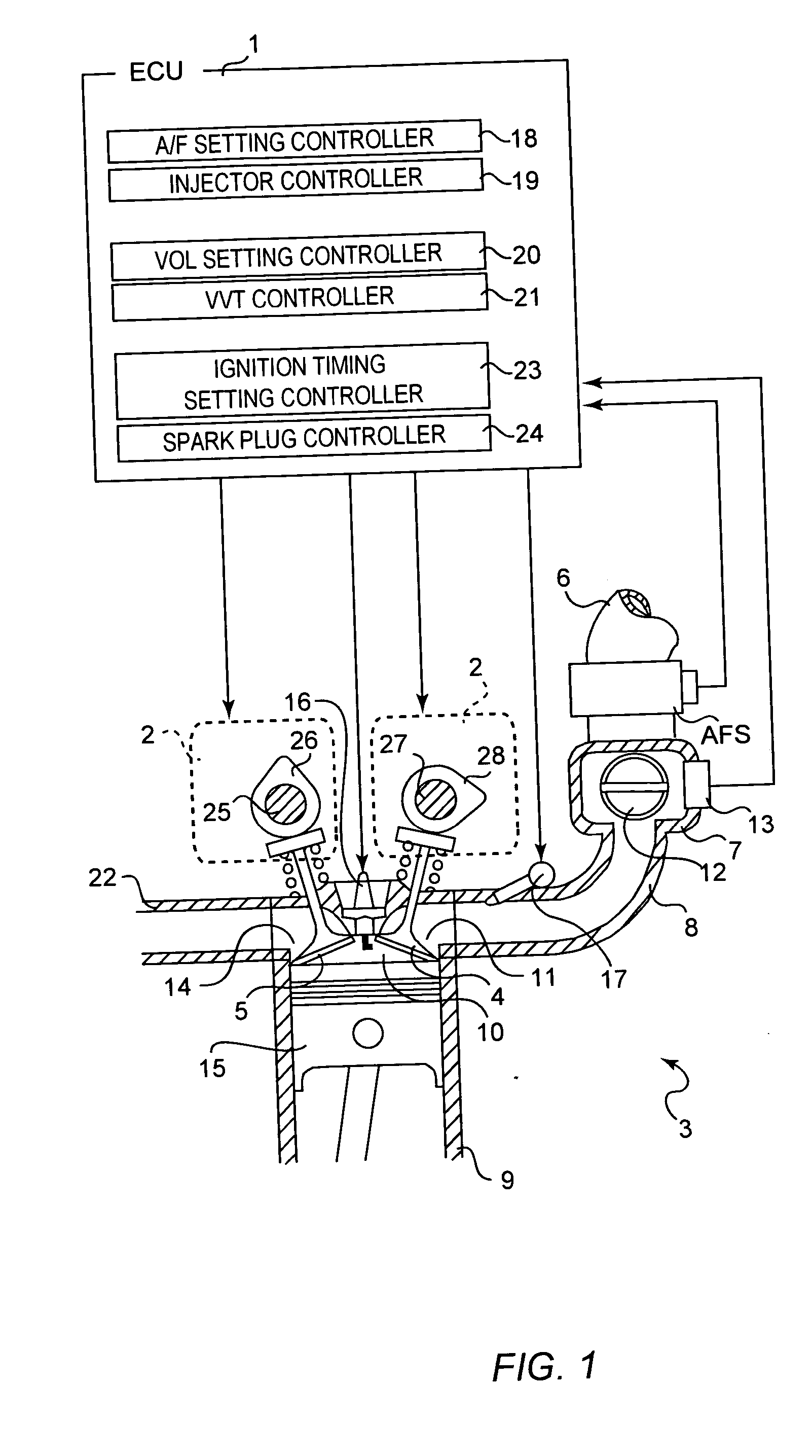
[0036] Referring to FIGS. 1 through 7, there is shown a variable valve timing controller (VVT controller) constructed in accordance with a preferred embodiment of the present invention.

[0037] The VVT controller consists mainly of an electronic control unit (ECU) 1 and variable valve timing mechanisms (VVT mechanisms) 2, as shown in FIG. 1. The VVT mechanism 2 is e.g., vane-type WT mechanism. They are respectively interposed between an exhaust camshaft 25, which drives an exhaust cam 26, and an exhaust cam sprocket (not shown) and between an intake camshaft 27, which drives an intake cam 28 and an intake cam sprocket (not shown). By the VVT mechanisms 2, the phase of the exhaust cam 26, which drives an exhaust-valve 5, with respect to a crankshaft (not shown) and the phase of the intake cam 28, which drives an intake-valve 4, with respect to the crankshaft can be varied. Accordingly, the intake- and exhaust-valves 4 and 5 can be opened and closed independently at different times.

[0...


PUM


Abstract

A variable valve timing controller includes an intake-valve and an exhaust-valve. When the engine is started, the intake-valve and the exhaust-valve are operated in a first mode in which the exhaust-valve is closed before top dead center and then the intake-valve is opened. And if a first predetermined condition is met, the intake-valve and the exhaust-valve are operated in a second mode in which the opening time of the intake-valve in the first mode is advanced before top dead center.

Description

CROSS-REFERENCE TO RELATED APPLICATION [0001] This application incorporates by references the subject matter of Application No. 2003-125848 filed in Japan on 30 Apr. 2003, on which priority claim is based under 35 U.S.C. §119(a). BACKGROUND OF THE INVENTION [0002] 1. Field of the Invention [0003] The present invention relates to a variable valve timing controller for an engine. [0004] 2. Description of the Related Art [0005] A wide variety of techniques have been developed and proposed in order to reduce the amount of hydrocarbon (HC) contained in the exhaust gas from an internal combustion engine. For example, Japanese Laid-Open Patent Publication No. 2002-13419 discloses a method in which exhaust gas are discharged through the intake port and the exhaust port by setting a valve overlap period (during which both the intake-valve and the exhaust-valve are open) before top dead center (TDC) (that is, before the piston reaches TDC on the exhaust stroke). It is also disclosed that with...

Claims


Application Information

Patent Timeline
IPC IPC(8): F02D13/02F02D41/06F02D43/00F02P5/15
CPCF02D13/0215F02D13/0261Y02T10/18F02D2013/0292F02D13/0265Y02T10/12A01G9/021A01G9/083
Inventor NAKAI, HIDEOMIYAMOTO, KATSUHIKOHOSHIBA, YOSHIYUKIMAEDA, KATSUYUKISHIOTA, SEIJI
Owner MITSUBISHI MOTORS CORP
Why Eureka
Try Eureka