
Device for sensing the axial position, in relation to the other component, of one of two components mobile relative to each other

a technology of axial position and sensor, which is applied in the direction of magnetic measurement, galvano-magnetic hall-effect devices, magnetic field measurement using galvano-magnetic devices, etc., can solve the problems of unfavorable radial installation space, undesirable enlargement of the total cylinder length, and high friction, so as to minimize the radial installation space required for the sensor device, the effect of commercially available relatively cheaply

Active Publication Date: 2005-01-06
FTE AUTOMOTIVE GMBH & CO KG
View PDF8 Cites 44 Cited by
  • Summary
  • Abstract
  • Description
  • Claims
  • Application Information

AI Technical Summary

Benefits of technology

[0013] The flux guide element allocated to the magnetic-flux-sensitive sensor and stationary in relation thereto, of the sensor device according to the invention serves virtually for bundling the field lines of the magnetic field of the magnetic signal element so that relatively high field strengths H arise in the flux guide element. In other words in the flux guide element there is a concentration of the magnetic flux Φ, the density of which i.e. the magnetic flux density B can be sensed by means of the magnetic-flux-sensitive sensor. The closer the magnetic signal element comes, during a movement along the flux guide element, to a measurement point on the flux guide element at which the magnetic flux density B in the flux guide element is sensed by means of the magnetic-flux-sensitive sensor, the higher the magnetic flux density B sensed.
[0027] Also two flux guide elements can be provided which run essentially parallel to each other and between which is inserted the magnetic-flux-sensitive sensor. Admittedly in this design of sensor device the signal detected, which is representative of the magnetic flux density B in the flux guide element, is weaker in comparison with a design with just one flux guide element. However, the two flux guide elements advantageously provide linearization of the signal shown over the relative travel of the magnetic signal element to the magnetic-flux-sensitive sensor, which simplifies analysis of the signal.

Problems solved by technology

This device is however only suitable within narrow limits for use on a conventional piston-cylinder arrangement, in particular as twisting of the radially magnetized rod magnet in relation to the Hall element must be prevented, usually causing a relatively high friction.
This requires a relatively large axial installation space in the piston for accommodation of the rod magnet which can also lead to undesirable enlargement of the total cylinder length.
A thicker design of the rod magnet however undesirably enlarges the radial installation space for accommodation of the rod magnet in the piston, not to mention the associated higher costs for the rod magnets, which is also undesirable in view of the large-scale use of such sensor devices.
This magnetic detector however only has a low signal yield i.e. the output voltage of the magneto-resistor here runs only with a very slight gradient over the travel of the magnet, for which reason in this state of the art it is at least difficult to design the signal analysis for precise determination of the distance traveled.
In addition, with this state of the art the magnetic body—which can also have the form of a frustoconical pyramid in other preferred embodiments—has a relatively high mass which is undesirable for particular applications.

Method used


Image

  • Device for sensing the axial position, in relation to the other component, of one of two components mobile relative to each other
  • Device for sensing the axial position, in relation to the other component, of one of two components mobile relative to each other
  • Device for sensing the axial position, in relation to the other component, of one of two components mobile relative to each other

Examples


Embodiment Construction

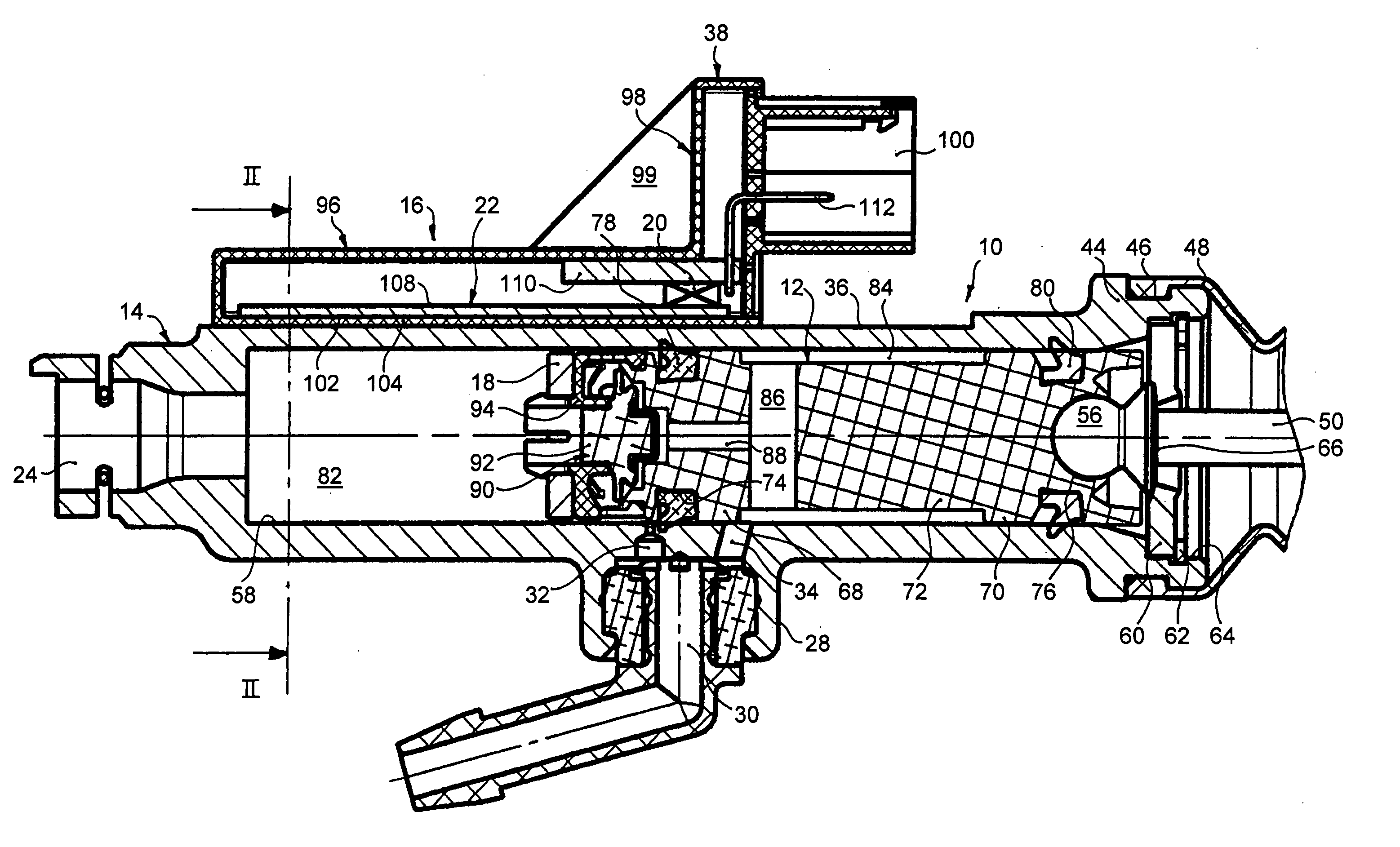
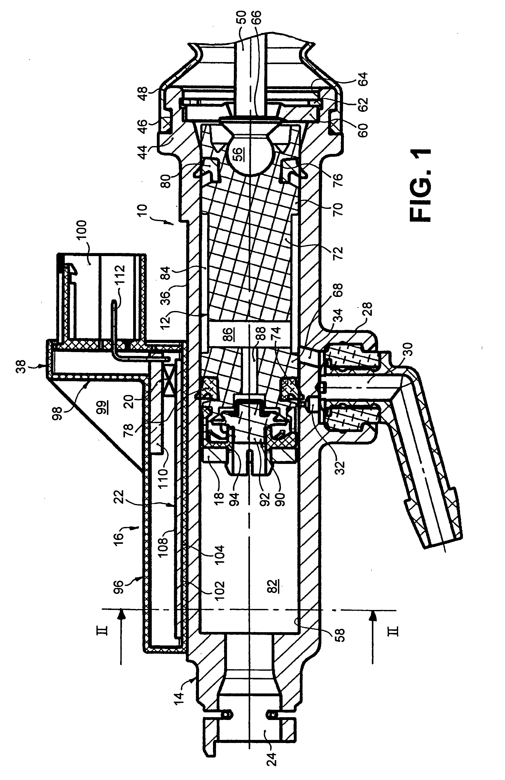
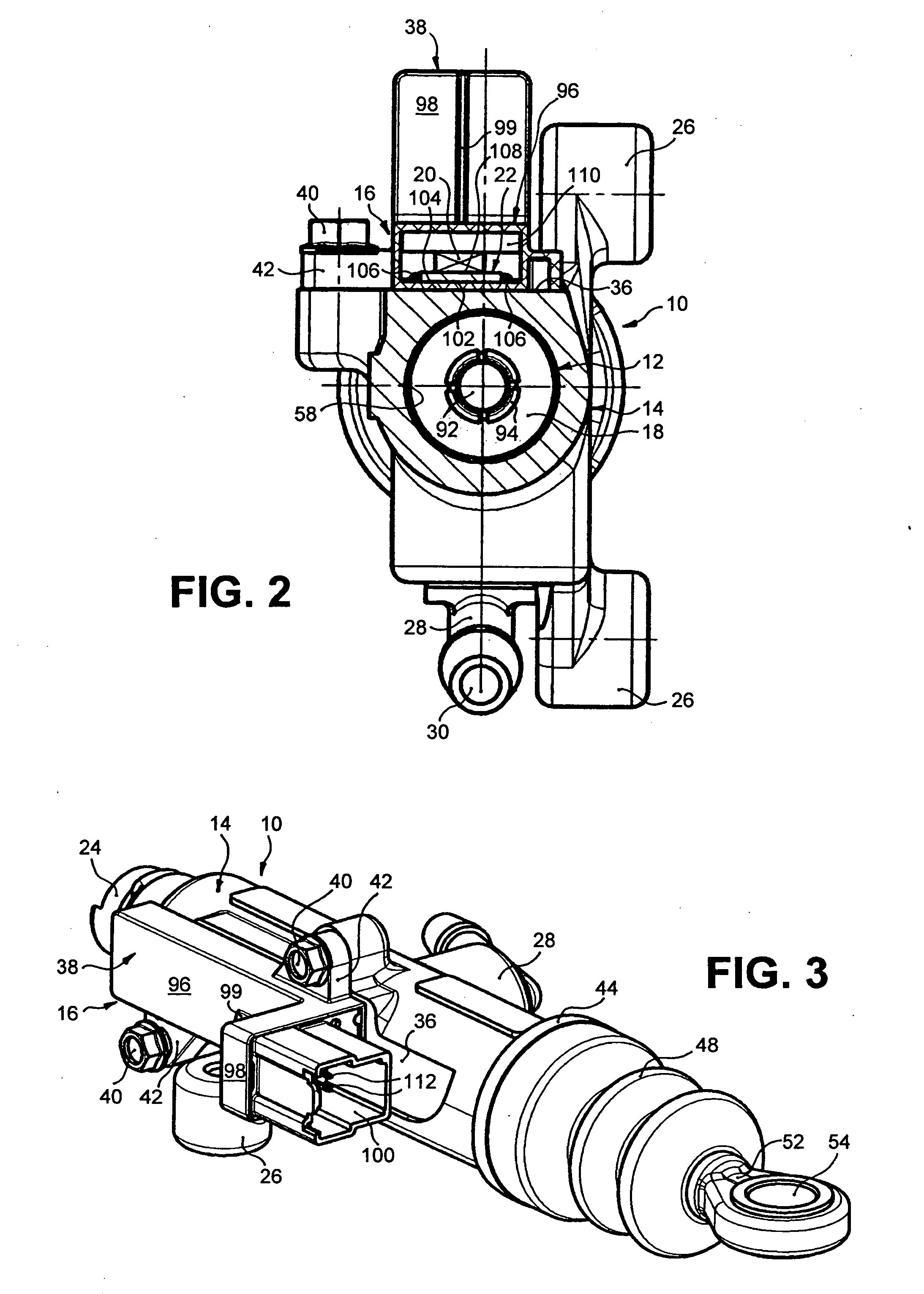
[0040] FIGS. 1 to 3 show as examples of a possible application of the present invention a master cylinder 10 for a hydraulic clutch control for motor vehicles which here has a piston 12, shown in its base position, which is held longitudinally mobile in a cylinder housing 14. 16 indicates generally a sensor device to sense the axial position of the piston 12 in relation to the cylinder housing 14, which has here arranged on the piston 12 a magnetic signal element in the form of an annular permanent magnet known as a ring magnet 18, and arranged on the cylinder housing 14 a magnetic-flux-sensitive sensor in the form of a Hall sensor 20, by means of which the axial relative position of the ring magnet 18 to the Hall sensor 20 can be detected in a manner to be described. As will also be described below, it is essential inter alia that at least one flux guide element 22, stationary in relation to the Hall sensor 20, is allocated to the Hall sensor 20 and extends on the cylinder housing ...


PUM


Abstract

A device is disclosed (16) for sensing the axial position, in relation to the other component, of one of two components mobile relative to each other, in particular a piston (12) in relation to a cylinder housing (14), which device has a magnetic signal element (18) arranged on the one component and a magnetic-flux-sensitive sensor (20, 20′) arranged on the other component, by means of which the axial relative position of the signal element to the sensor can be detected. According to the invention, allocated to the sensor is at least one flux guide element (22, 22′) stationary in relation to the sensor, which extends on the other component at least over the area to be detected of the axial relative positions of the signal element to the sensor and comprises a plate section of a magnetizable material, wherein the sensor is arranged at one longitudinal end of the flux guide element outside the area to be detected of axial relative positions. The result is a simple sensor device by means of which, with little installation space required, any arbitrary axial relative positions between the components concerned or their relative travel can be detected reliably.

Description

TECHNICAL FIELD [0001] The invention relates to a device for sensing the axial position, in relation to the other component, of one of two components mobile relative to each other according to the preamble portion of claim 1. In particular the invention relates to a device for sensing the axial position of a piston in relation to a cylinder housing of a master or slave cylinder for a hydraulic clutch control for motor vehicles, as is used in large quantities in the automotive industry. STATE OF THE ART [0002] A conventional hydraulic clutch control for motor vehicles has a master cylinder which is connected to a reservoir filled with hydraulic fluid and which for example can be activated via a clutch pedal or an electro-motor drive. The master cylinder is hydraulically connected via a pressure line with a slave cylinder so that the pressure generated by pressing the clutch pedal or by electro-motor movement of the master cylinder piston in the master cylinder can be transferred via ...

Claims


Application Information

Patent Timeline
IPC IPC(8): F15B15/28F16D25/08F16D48/02
CPCF16D25/088F16D25/14F15B15/2861F16D2300/18G01D5/145F16D48/02F16D25/08F16D2025/081
Inventor WOHNER, STEFFEN
Owner FTE AUTOMOTIVE GMBH & CO KG
Learn More