Metrological digital audio reconstruction

a digital audio and audio reconstruction technology, applied in the field of recorded analog signals, can solve the problems of only suited archival methods, noise addition and resolution degradation, and achieve the effect of reducing noise in the audio reconstruction

Inactive Publication Date: 2005-01-06
RGT UNIV OF CALIFORNIA
View PDF1 Cites 16 Cited by
  • Summary
  • Abstract
  • Description
  • Claims
  • Application Information

AI Technical Summary

Benefits of technology

As with transverse interpolation, one may practice longitudinal curve fitting of the tracked spatial location for minimized error from the short transverse profile portion, and then transforming the tracked spatial location into the audio extraction. Such longitudinal curve fitting may be tailored to correct for media defects such as wow, flutter, offset spiral of Archimedes due to a mispositioned central hole relative to the groove center of rotation, tracking error, acylindrical deformations, or other effects.
Both the transverse and longitudinal interpolation methods have the practical application of reducing noise in the audio reconstruction.

Problems solved by technology

This retrieval method includes the extra step of traditional silver chemistry film photography, which may also add noise and degrade resolution.
This archival method is only suited to lateral groove disc media and cannot accommodate cylinders or other vertically modulated media.
Furthermore, this system maps the three-dimensional features of recorded grooves to a two-dimensional medium, thereby discarding the full three-dimensional information available in the original groove.
This approach has only poor resolution due to the weak proportional relationship between actual surface height and grey-scale response.
However, the desk-top scanners have insufficient resolution to capture the subtle deflections of groove modulation in the media, and are also limited by a faulty assumed proportionality of grey-scale versus surface feature height.
It cannot accommodate three dimensional media such as cylinder.

Method used


Image

  • Metrological digital audio reconstruction
  • Metrological digital audio reconstruction
  • Metrological digital audio reconstruction

Examples


Embodiment Construction

1. Definitions

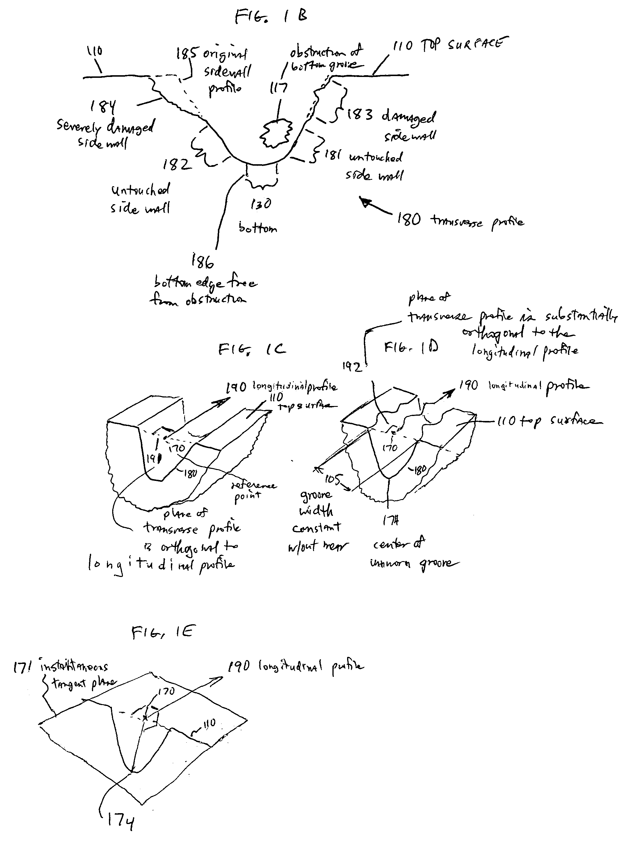
“Profile” means a variation of the elevation of a feature versus position.

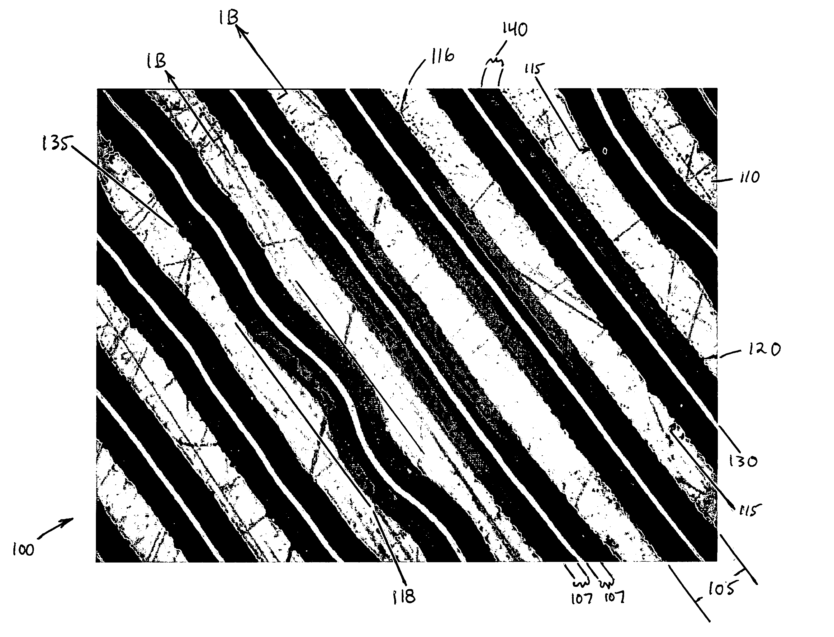
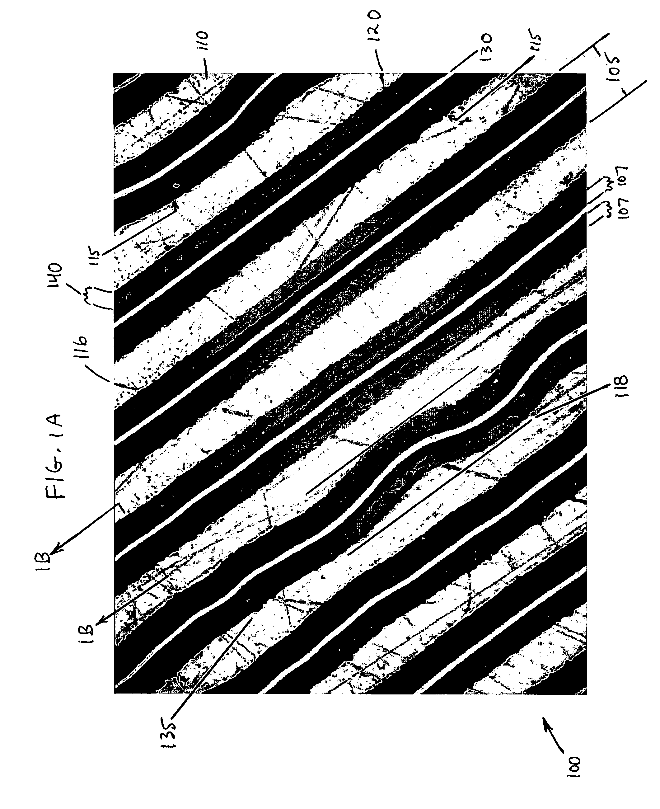
“Transverse profile” means the cross-section of a mechanical groove taken in the shorted direction, orthogonal to the instantaneous average longitudinal path of the mechanical groove.

“Longitudinal profile” means the elevation of the path of a mechanical groove as it follows the surface of a medium. The mean longitudinal profile path at every point is orthogonal to a corresponding transverse profile.

“Mechanical groove” means any spatially modulated feature covering a portion of a surface, and typically having at least a portion of a transverse profile approaching a constant profile.

“Tangent” means a line coplanar with a tangent plane constructed so as to pass through a point on the surface of a medium defined by a mathematical function.

“Surface” means a bulk surface of a medium defined by a mathematical function averaged over a spatial distance of a plurality of mechanical grooves.

“Positiv...


PUM

PropertyMeasurementUnit
sizeaaaaaaaaaa
sizeaaaaaaaaaa
frequencyaaaaaaaaaa

Abstract

Audio information stored in the undulations of grooves in a medium such as a phonograph record may be reconstructed, with little or no contact, by measuring the groove shape using precision metrology methods coupled with digital image processing and numerical analysis. The effects of damage, wear, and contamination may be compensated, in many cases, through image processing and analysis methods. The speed and data handling capacity of available computing hardware make this approach practical. Two examples used a general purpose optical metrology system to study a 50 year old 78 r.p.m. phonograph record and a commercial confocal scanning probe to study a 1920's celluloid Edison cylinder. Comparisons are presented with stylus playback of the samples and with a digitally re-mastered version of an original magnetic recording. There is also a more extensive implementation of this approach, with dedicated hardware and software.

Description

REFERENCE TO SEQUENCE LISTING, TABLE, OR COMPUTER PROGRAM APPENDIX Attached hereto and incorporated by reference is a compact disc recording of five short sound tracks. Track 1 is an optically reconstructed version of a 78 r.p.m. shellac disc corresponding to FIG. 5A, with duration of approximately 19 seconds. Track 2 is a mechanical stylus playback version of same physical disc of Track 1, and corresponds to FIG. 5B. Track 3 is a version from commercial compact disc reissue of the original source material of FIGS. 5A and B, based upon original studio magnetic tape masters, and corresponds to FIG. 5C. Track 4 is an optically reconstructed version of a 160 r.p.m. celluloid cylinder entitled “Edison Blue Amberol”, with duration of approximately 24 seconds, and corresponds to FIG. 9A. Track 5 is a mechanical stylus playback version of same source material (using a different physical cylinder) of Track 4, and corresponds to FIG. 9B. BACKGROUND OF THE INVENTION 1. Field of the Inv...

Claims


Application Information

Patent Timeline
Patent Type & Authority Applications(United States)
IPC IPC(8): G11B3/70
CPCG11B3/70
Inventor FADEYEV, VITALIYHABER, CARL
Owner RGT UNIV OF CALIFORNIA
Why Eureka
Try Eureka