Attenuator and portable telephone terminal apparatus using the same

a technology of portable telephone terminals and attenuators, which is applied in the direction of electrical devices, radio transmission, and automatic control, etc., can solve the problems of increasing the code error rate, the leakage power to adjacent channels, and the far-near problem, so as to reduce the number of voltages to be applied, simplify the circuit configuration, and high accuracy

Inactive Publication Date: 2005-01-06
COLLABO INNOVATIONS INC
View PDF15 Cites 10 Cited by
  • Summary
  • Abstract
  • Description
  • Claims
  • Application Information

AI Technical Summary

Benefits of technology

According to the invention, a single reference voltage Vref in place of the voltages VDD(A) and VDD(B) is applied to the attenuator 277 (272A and 272B). Further, a battery supply voltage or the like is applied selectively to the amplifiers 242 and 244 or the amplifiers 252 and 254, so that band selection is performed. In this case, the attenuator 272 does not perform band selection. However, gain control is performed using a single gain control voltage and a single reference voltage. This avoids the necessity of the control of the voltages VDD(A) and VDD(B) in the portable telephone terminal apparatus, in contrast to the prior art. This permits band selection and gain control with extremely high accuracy.
Further, the same reference voltage is applied to the source electrodes of the series field effect transistors on one side and the series field effect transistors on the other side and to the gate electrodes of the shunt field effect transistors on one side and the shunt field effect transistors on the other side. This permits accurate control against a fluctuation in the reference voltage. Further, this reduces the number of voltages to be applied, and hence simplifies the circuit configuration.
When the series and shunt field effect transistors have a high threshold voltage, the reference voltage can be set to be a reference voltage such as a ground voltage. This avoids completely the necessity of considering the fluctuation in the reference voltage. Thus, setting is necessary only for the control voltage. This simplifies the design, and permits accurate gain control. Further, this eliminates the necessity of the reference voltage, and hence simplifies the circuit configuration.
As described above, according to the invention, in an attenuator, regardless of band selection, variable resistors of respective bands perform similar gain control operation on the basis of the same gain control voltage, so that the variable resistor of the selected band substantially continuously controls the output of the power amplifier, and that the gain control is performed by a single gain control voltage. This avoids a difference in the gain during the band selection, and hence permits gain control operation with extremely high accuracy during the band selection.
As a result, in a portable telephone terminal apparatus provided with the above-mentioned attenuator, regardless of band selection, avoided is the necessity of the adjustment of the gain control voltage at the time of band selection, and hence resolved is the problem of delay caused by the transient response time in the drain voltage applied to each attenuator. This avoids the problem that the output Pout of the portable telephone terminal apparatus temporarily deviates from the desired line at the time of band selection. Thus, high quality speech is achieved. Further, in the band selection in the high frequency section, merely a single reference voltage is sufficient for the setting of the drain voltage to the attenuator. This simplifies the control of band selection. Further, the high frequency section does not need attenuators for respective bands. This reduces space requirement and the size.

Problems solved by technology

This issue is called the far-near problem.
In case that the gain control is not satisfactorily performed in the transmitting section of the portable telephone terminal apparatus, when the distance of the portable telephone terminal apparatus from the base station decreases, the intensity of the radio waves delivered to the base station increases, and hence causes an increase in the leakage power to adjacent channels.
This causes an increase in the code error rate, and hence degrades the speech quality.
Nevertheless, at the time of band selection, the output Pout of the portable telephone terminal apparatus temporarily deviates from the line at the time of band selection because of the delay in the follow operation caused by the time delay in the feedback control and because of the discontinuity in the output level at the band selection.
This has caused the problem of voice disturbance and hence of degradation in the voice quality.
This problem has been described for the case that the portable telephone terminal apparatus moves under ideal conditions.
Nevertheless, actual conditions during the move are more adverse.
Thus, the above-mentioned problem should occur frequently that the intensity of the received signal in the base station deviates from a normal value so that the voice quality degrades.
This causes complexity in the control in the controlling section 110.
This causes complexity in the circuit configuration, as well as an increase in space requirement.
This has caused the problem of an increase in the overall size of the portable telephone terminal apparatus.

Method used


Image

  • Attenuator and portable telephone terminal apparatus using the same
  • Attenuator and portable telephone terminal apparatus using the same
  • Attenuator and portable telephone terminal apparatus using the same

Examples


embodiment 1

of the invention is described below with reference to FIGS. 1-7.

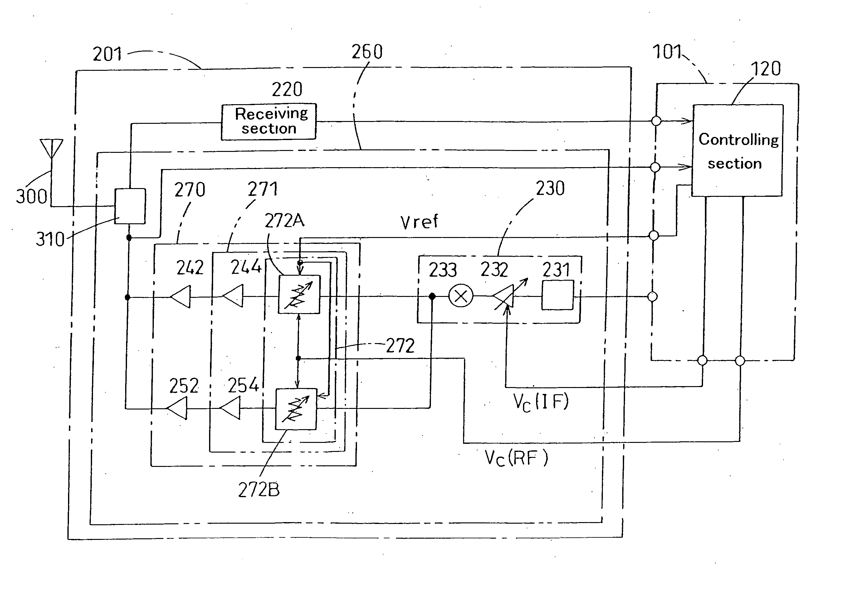
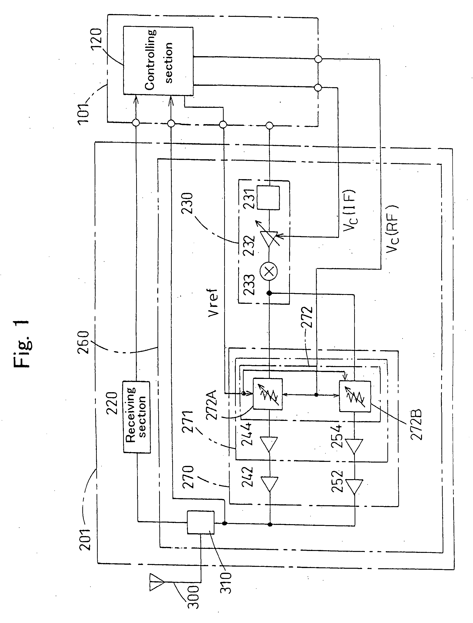
FIG. 1 is a block diagram showing the configuration of a portable telephone terminal apparatus according to Embodiment 1 of the invention. The configuration and the operation of the portable telephone terminal apparatus according to Embodiment 1 are described below with reference to FIG. 1. As shown in FIG. 1, the portable telephone terminal apparatus is constructed from a microcomputer logic section or the like, and comprises: a baseband section 101 for processing a voice signal; and a radio section 201 for receiving the voice signal processed in the baseband section 101 and then performing communication with a base station.

The radio section 201 comprises: a transmitting section 260 for generating a transmission signal to be transmitted to the base station; and a receiving section 220 for receiving a transmission signal transmitted from the base station.

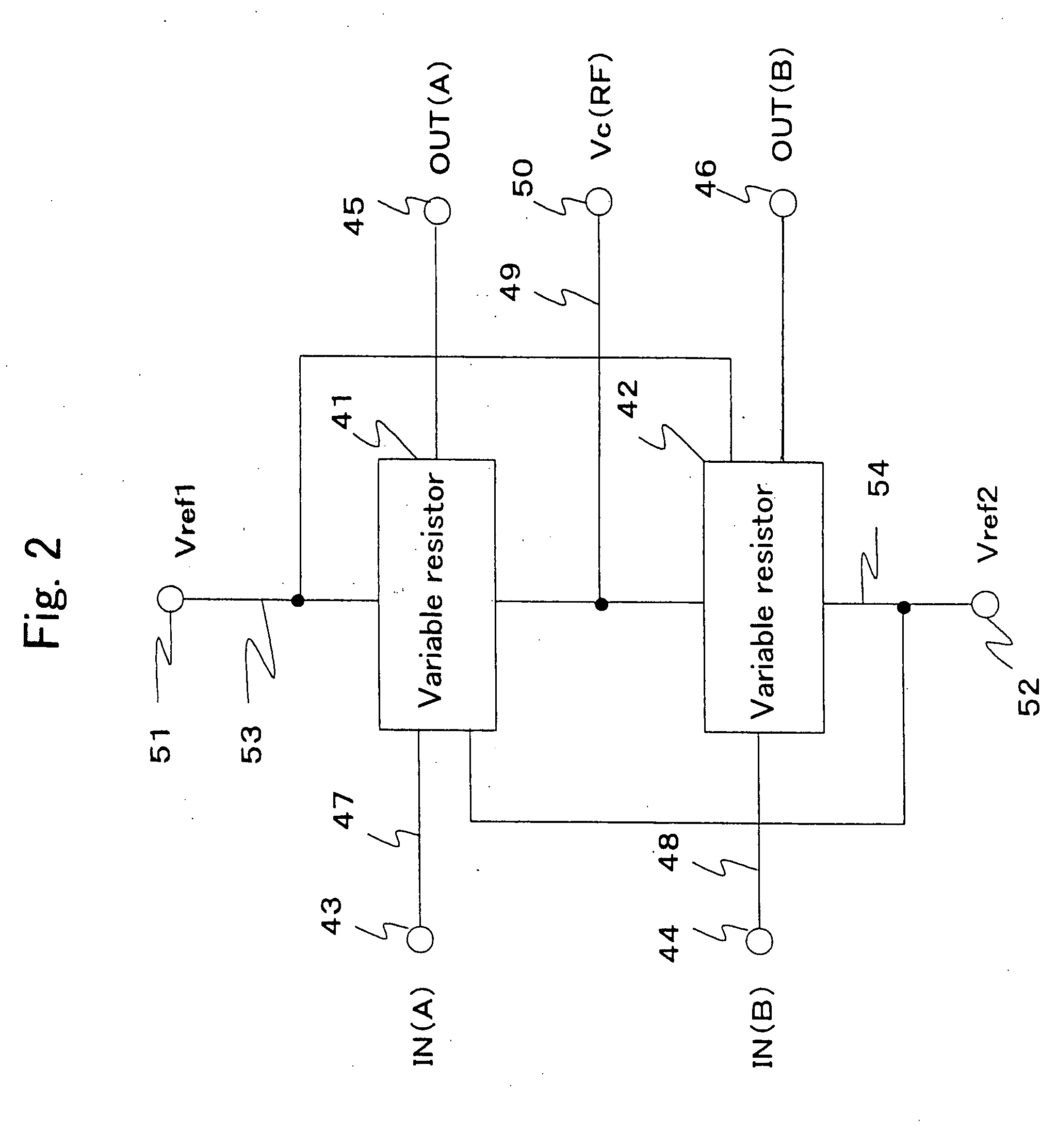
The transmitting section 260 comprises: an intermediate freque...


PUM


Abstract

Provided are: at least one or more series variable resistors implemented by field effect transistors connected to a signal line A; and at least one or more shunt variable resistors implemented by field effect transistors connected between a signal outputting section A and a reference potential section GND. Further provided are: at least one or more series variable resistors implemented by field effect transistors connected to a signal line B arranged in parallel to the signal line A; and at least one or more shunt variable resistors implemented by field effect transistors connected between a signal outputting section B and a reference potential section GND.

Description

BACKGROUND OF THE INVENTION 1. Field of the Invention The present invention relates to a dual band (mode) portable telephone terminal apparatus and, in particular, to the configuration of an attenuator in a high frequency section inside a radio section of the apparatus. The attenuator according to the invention permits high quality speech through the portable telephone terminal apparatus, and hence is useful as an attenuator in a high frequency section inside a radio section of a dual band (mode) portable telephone terminal apparatus. 2. Related Art of the Invention In a digital system (such as PDC), the intensity of radio waves delivered from a portable telephone terminal apparatus to abase station needs to be maintained at constant independently of the distance between the portable telephone terminal apparatus and the base station. For this purpose, gain control is performed in a transmitting section in the portable telephone terminal apparatus. FIG. 9 schematically shows the ...

Claims


Application Information

Patent Timeline
Patent Type & Authority Applications(United States)
IPC IPC(8): H03G3/10H03G3/30
CPCH03G3/3042
Inventor INAMORI, MASAHIKOTAKAGI, TSUNEHIRONAKAYAMA, MASAOMOTOYOSHI, KANAME
Owner COLLABO INNOVATIONS INC
Why Eureka
Try Eureka