Corrosion sensor

a technology of corrosion sensor and corrosion sensor, which is applied in the direction of liquid/fluent solid measurement, material electrochemical variables, instruments, etc., can solve the problems of high humidity, high salinity, and seawater tanks, and achieves easy comparison of ship tanks, easy integration, and fast

Inactive Publication Date: 2005-01-13
THE UNITED STATES OF AMERICA AS REPRESENTED BY THE SECRETARY OF THE NAVY
View PDF3 Cites 30 Cited by
  • Summary
  • Abstract
  • Description
  • Claims
  • Application Information

AI Technical Summary

Benefits of technology

Another object is to provide a fast, objective, effective method for easily comparing ship tanks according to which is most in need of maintenance.
Another object is to provide a corrosion monitoring system which is easily integrated into a condition based monitoring program for a ship.

Problems solved by technology

Seawater tanks, used in many ballasting operations, are subject to high salinity conditions, high humidity, the attachment of biological materials to the surfaces and repeated fill / drain cycling.
These tanks also contain a significant percentage of structural components, which are difficult to prepare and coat effectively.
Overhead coated surfaces, while often wet from condensation and high humidity, fail by effects of gravity and osmotic pressure directly at the coatings surfaces.
While each of these areas are exposed to similar conditions, in general, failures for different surfaces may occur at different rates and by different mechanisms.
Those tanks located on the ship exterior may additionally receive solar energy and suffer from highly variable temperature and heat cycling effects.
No coating system is perfect, and if a coating is damaged, the exposed bare tank metal will be subjected to the tank fluid, with the exposed area being aggressively attacked and corroded.
Even if the damage to the coating is small, corrosion begins, and over time, tends to undercut the intact coating around the damage thus enlarging the area of attack and damage.
Coatings damage is a progressive event and a large number of small damage spots can contribute to significant damage.
Over time, the coatings system begins to fail and more bare area is exposed.
Mechanical damage plays a role, but the coating itself also adsorbs moisture slowly and moisture eventually reaches the metallic surface where corrosion begins.
Imperfect or poor coating application may accelerate the moisture absorption effects or target areas which fail sooner.
Eventually, tank coatings failure occurs when the percentage of damage becomes intolerably high or when the cathodic protection system (sacrificial anodes within the tank) can no longer supply enough current with which to protect the amount of bare area.
Maintenance costs in a tank are extremely costly, because the tank requires staging, grit blasting recoating, and installation of fresh sacrificial anodes, under controlled environmental conditions and all in a very difficult non-uniform geometry.
Ships with many tanks cannot repaint all tanks on a routine basis and port engineers, with highly limited resources, must decide which tanks must be recoated and when.
d) Failure related to substandard coatings.
The geometry is often unique for each tank and maintenance procedures are often complicated by many complex structural members and baffles.
Working conditions within the tanks are often awkward, difficult, and potentially dangerous.
This method of inspection is costly, time-consuming, and typically subjective in nature.
The subjective nature of a visual inspection and difficulty in observing many areas of the tanks may result in missed areas, misinterpretation of corrosion damage, or poor assessment of general coatings deterioration.
Further, such a fast, inexpensive tank monitoring and inspection system would allow scarce resources to be devoted to actual tank maintenance, rather than to labor intensive visual inspection.
If tank maintenance is incorrectly scheduled, based upon inaccurate and dated human inspections, unnecessary funds may be expended to refurbish areas that do not have critical need, and other necessary maintenance, which had been deferred in favor of the tank maintenance, may go undone.
No convenient, long term monitoring system is available using standard half-cells, however.

Method used


Image

  • Corrosion sensor
  • Corrosion sensor
  • Corrosion sensor

Examples


Embodiment Construction

Reference will now be made in detail to the present preferred embodiments of the present invention, examples of which are illustrated in the accompanying drawings, wherein like reference numerals refer to like elements throughout.

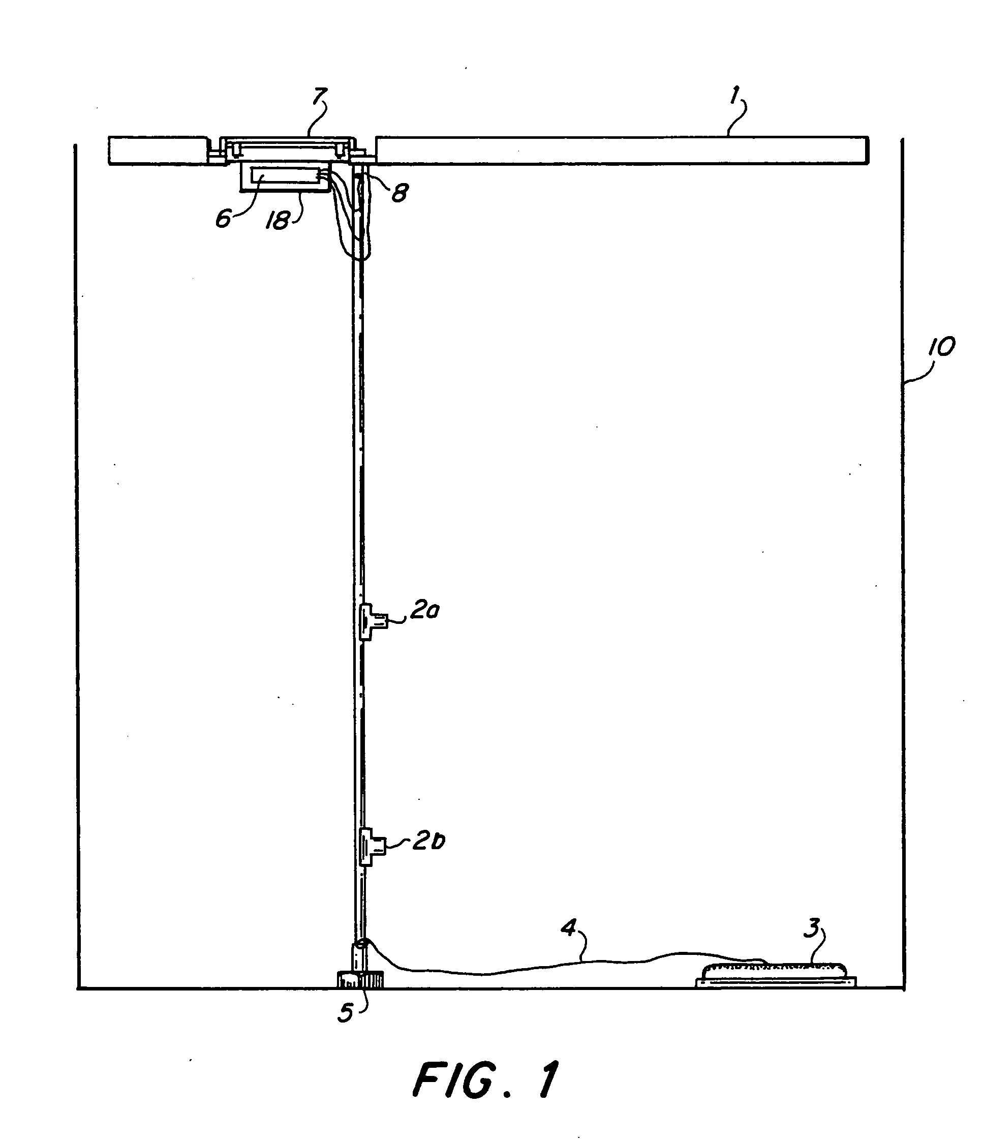
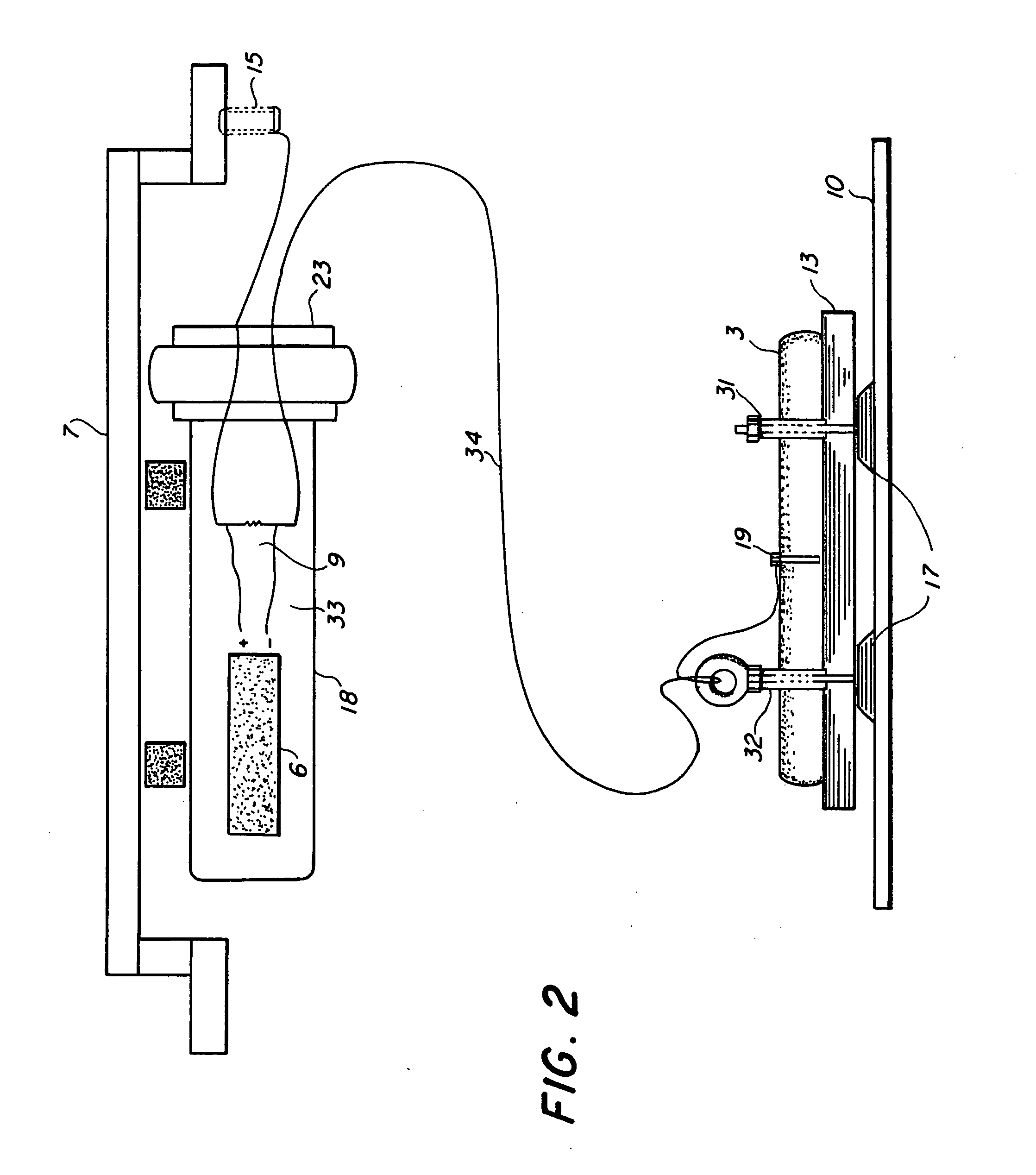
FIG. 1 is a diagram illustrating a preferred embodiment of a tank corrosion monitoring system 1 for use within a tank 10, according to a preferred embodiment of the present invention. The corrosion monitoring system 1 is a self contained package intended for in-situ installation within an individual ballast or compensated fuel tank. The corrosion monitoring system 1 includes: two reference half cells 2a and 2b, an instrumented sacrificial anode 3, a cable 4 for suspending the reference half cells 2a and 2b within the tank 10, a magnetic cable tensioner 5, a datalogger 6 for storage of voltage and current data, and a waterproof electronics enclosure 18.

The two potential reference half-cells 2a and 2b, shown in FIG. 1, are Silver / Silver Chloride (Ag / AgCl)...


PUM

PropertyMeasurementUnit
cathodic surface areaaaaaaaaaaa
currentaaaaaaaaaa
currentaaaaaaaaaa

Abstract

A system using tank corrosion sensors to provide for an overall assessment and monitoring of the electro-chemical corrosion and coatings condition in ships' tanks, and particularly in ships' seawater or compensated fuel tanks. The system includes reference half-cells mounted along a suspended cable and one instrumented sacrificial anode at the end of the cable to provide optimal sensing capability within a tank structure. The reference half-cells and the sacrificial anode measure a potential and current output, respectively. Together the measurements provide objective information that can be used to predict corrosion damage and coating deterioration occurring throughout the structure of the tank. The system may be used for an overall assessment and monitoring of the electrochemical corrosion and coatings condition. In a preferred embodiment, the measurements are stored in a datalogger that is optimally contained within an associated instrument housing. If used with other systems in other tanks, the system may be used to monitor the relative tank condition, trend tank condition changes over time, range tank behavior into three categories and provide a direct analysis methodology for making tank maintenance decisions.

Description

BACKGROUND OF THE INVENTION 1. Field of the Invention The present invention relates to an corrosion monitoring system, which is used to provide an overall assessment of the materials degradation and the condition of protective coatings in a tank structure in which the metal is subject to corrosion, and particularly relating to a corrosion sensor for use in tanks which contain or intermittently contain conductive electrolyte. 2. Description of the Related Art Shipboard tanks make up a significant percentage of below deck space in ships and vessels. These tanks are necessary components for the storage of liquids, for example, ballast seawater, compensated fuel / seawater, and a number of other essential liquids. The size and quantity of these tanks vary considerably for each class of ship. Each tank on a ship has a unique geometry, operational use and a set of corresponding environmental factors in which the metals and coatings are exposed. Seawater tanks, used in many ballasting op...

Claims


Application Information

Patent Timeline
Patent Type & Authority Applications(United States)
IPC IPC(8): G01N17/02
CPCG01N17/02
Inventor THOMAS, E. D. IIILUCAS, K. E.SLEBODNICK, PAULHOGAN, ELIZABETH A.
Owner THE UNITED STATES OF AMERICA AS REPRESENTED BY THE SECRETARY OF THE NAVY
Why Eureka
Try Eureka