
Comminution apparatus

Inactive Publication Date: 2005-01-13
ATI PROPERTIES
View PDF9 Cites 33 Cited by
  • Summary
  • Abstract
  • Description
  • Claims
  • Application Information

AI Technical Summary

Benefits of technology

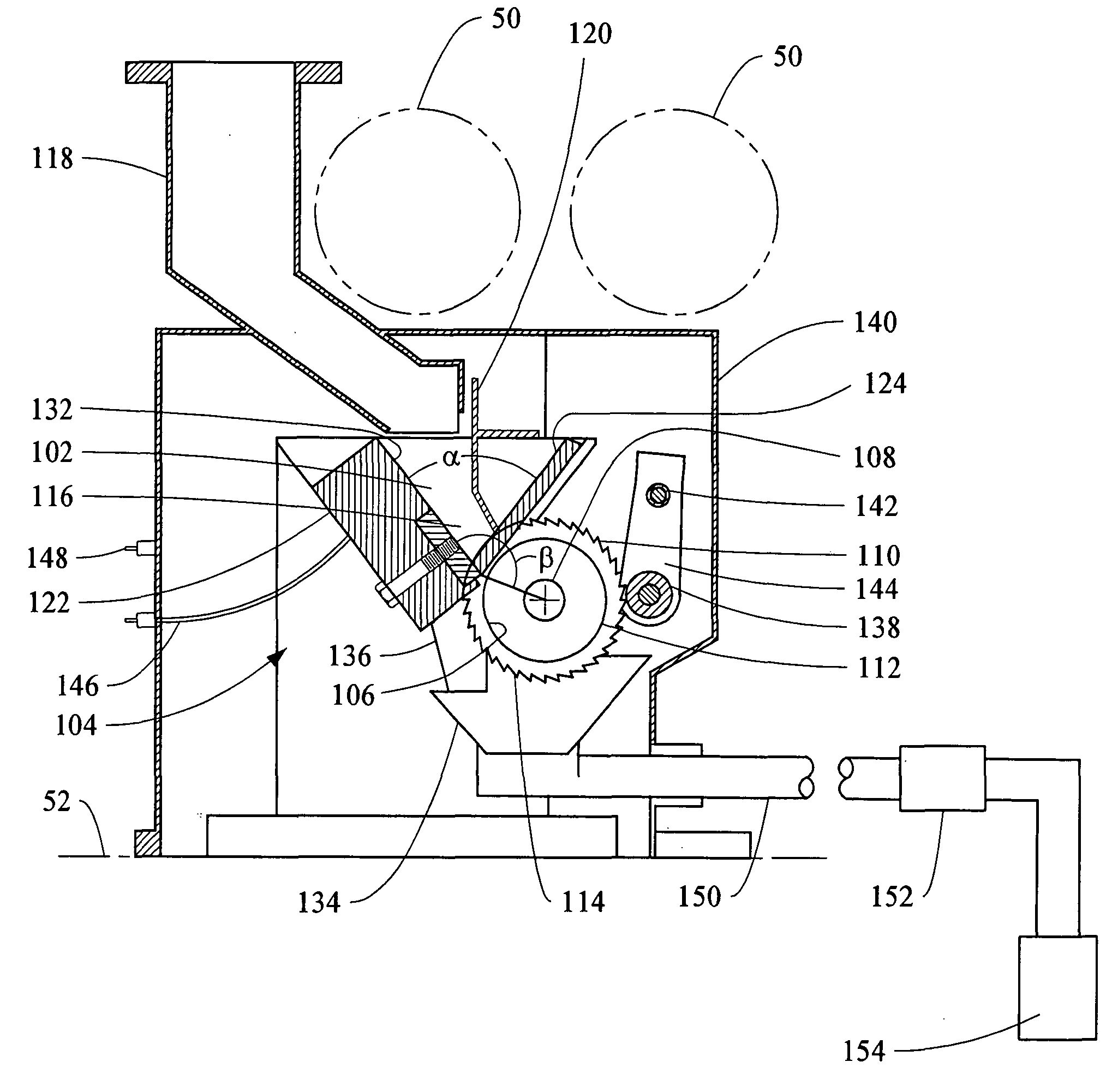
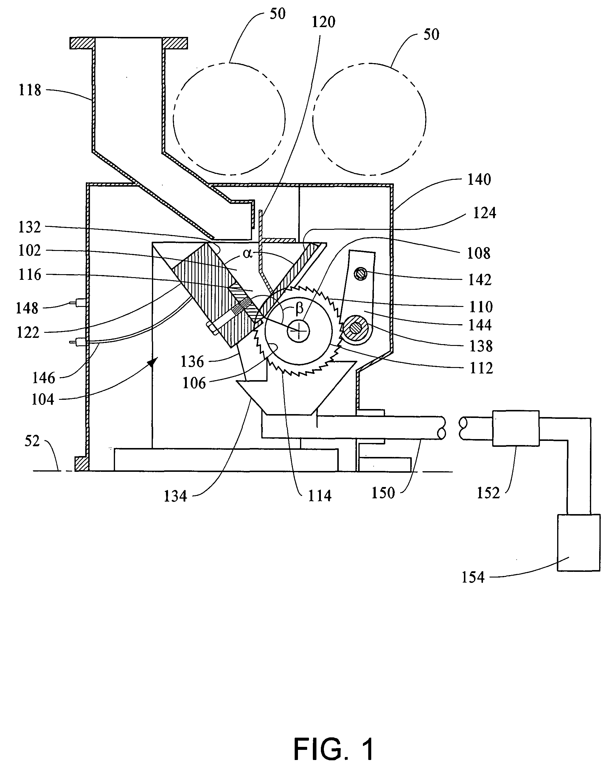
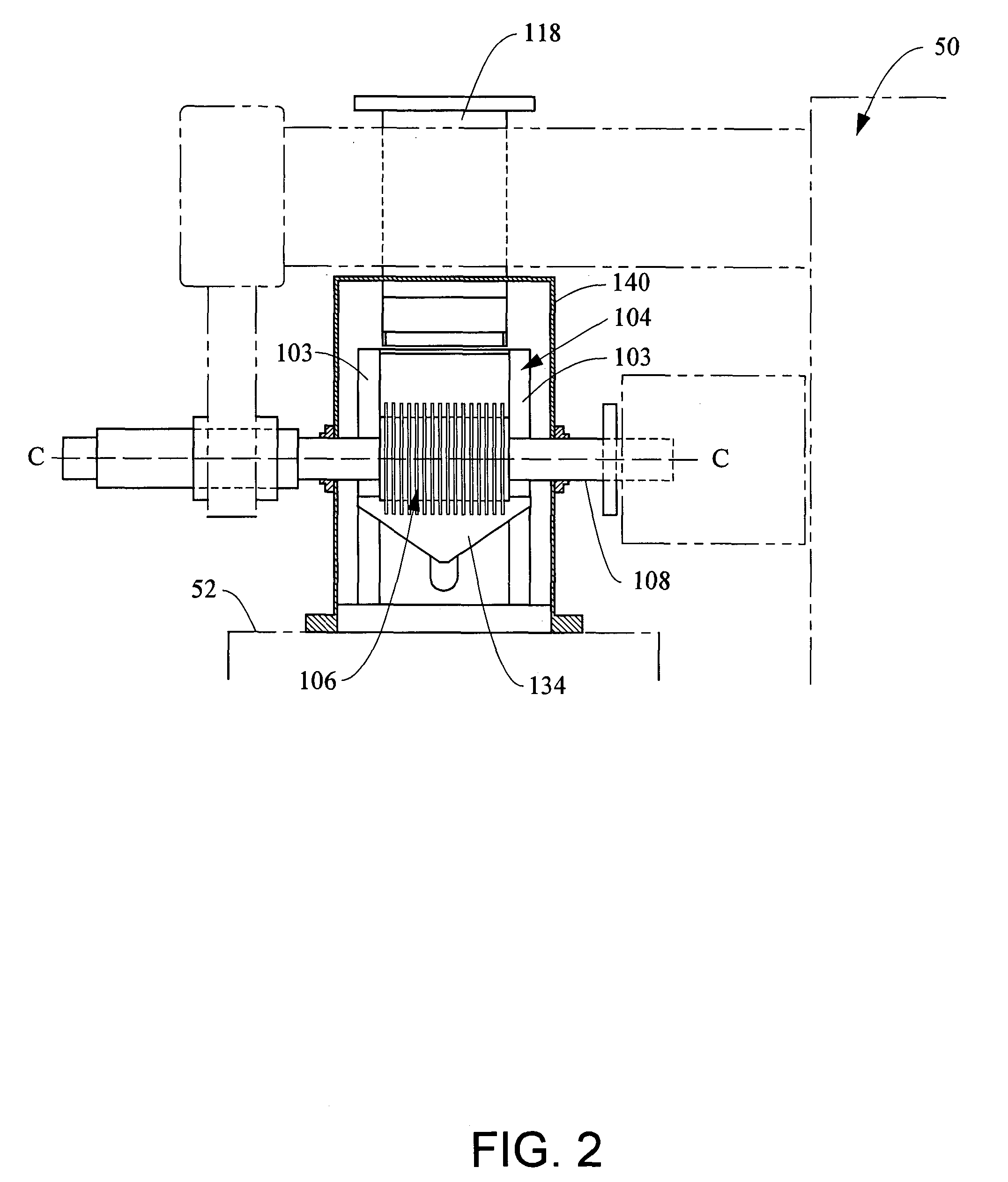
[0003] One embodiment of the present invention provides a comminution apparatus for reducing a feed material to a desired size. The comminution apparatus includes a cutting chamber defining an interior volume. The cutting chamber includes a first member and a second member forming an angle therebetween. Each of the first member and the second member include a plurality of slots therethrough providing access to the interior volume. The apparatus further includes a rotatable arbor disposed outside the interior volume of the cutting chamber. The arbor supports a plurality of toothed blades thereon. During rotation of the arbor, a portion of each of the blades enters the interior volume of the cutting chamber through the slots in the first member and exits the interior volume of the cutting chamber through the slots in the second member.
[0004] The present invention also is directed to a method for re

Problems solved by technology

Certain materials, such as light metals, including zirconium, titanium and niobium, for example, cannot be effectively reduced (i.e., comminuted) to fine powder using crushers because these metals have a tendency to gall, and chips of the metals would stick to the cutting edges.
This process is expensive and may still produce powder containing unacceptably high levels of hydrogen and oxygen.

Method used


Image

  • Comminution apparatus
  • Comminution apparatus
  • Comminution apparatus

Examples


Embodiment Construction

[0015] Referring now to the drawings for the purpose of illustrating the present invention and not for the purpose of limiting the same, it is to be understood that certain standard components or features that are within the purview of an artisan of ordinary skill and do not contribute to the understanding of the various embodiments of the invention are omitted from the drawings to enhance clarity. In addition, it will be appreciated that the characterizations of various components and orientations described herein as being “vertical” or “horizontal”, “right” or “left”, “side”, “top” or “bottom”, or the like are relative characterizations only and are based upon the particular position or orientation of a given component for a particular application.

[0016]FIG. 1 is a sectional view of an embodiment of a comminution apparatus 100 supported on a table 52 of a milling machine 50, components of which are shown in dotted lines. The milling machine 50 may be, for example, a 15 HP Kearney...


PUM


Abstract

A comminution apparatus for reducing a particle size of a material includes a cutting chamber defining an interior volume, wherein the cutting chamber includes first and second member forming an angle therebetween. Each of the first and second members include a plurality of slots therethrough providing access to the interior volume. The apparatus further includes a rotatable arbor disposed outside the interior volume of the cutting chamber and supporting a plurality of toothed blades thereon. During rotation of the arbor a portion of each of the blades enters an interior volume of the cutting chamber through the slots in the first member and exits the interior volume of the cutting chamber through the slots in the second member. The comminution apparatus may be used to process various feed materials to desired sizes, and is particularly useful for reducing the size of materials otherwise difficult to cut to small size. Such materials include, for example, zirconium, titanium, magnesium, niobium, calcium, copper, potassium, hafnium and aluminum

Description

BACKGROUND OF THE INVENTION [0001] Several different types of equipment are used for size reduction or comminution of materials to fine particles or powder. Crushing rolls, rock crushers, hammer mills and ball mills are examples of such equipment, and are generically referred to herein as “comminution apparatus”. The decision to select a particular type of comminution apparatus depends, at least in part, on the size distribution desired for the resulting product and on the properties of the feed material. Crushing rolls, for example, may be particularly suitable for coarse size reduction of brittle materials and for materials that fracture under pressure without smearing or flowing. [0002] Certain materials, such as light metals, including zirconium, titanium and niobium, for example, cannot be effectively reduced (i.e., comminuted) to fine powder using crushers because these metals have a tendency to gall, and chips of the metals would stick to the cutting edges. To address this pr...

Claims


Application Information

Patent Timeline
IPC IPC(8): B02C18/16B02C18/18
CPCB02C18/16B02C2018/188B02C18/18
Inventor ROBERTS, JAMES D.
Owner ATI PROPERTIES
Learn More