Stacked-type semiconductor device
a semiconductor and stacked technology, applied in the direction of solid-state devices, basic electric elements, electrical apparatus construction details, etc., can solve the problems of difficult to effectively reduce the thickness of the device as a whole, and the configuration may not be advantageous in terms of saving production costs, so as to reduce the thickness of the device, reduce the cost, and reduce the defect of the electrode terminal connection portion due to the bending of the wiring substra
- Summary
- Abstract
- Description
- Claims
- Application Information
AI Technical Summary
Benefits of technology
Problems solved by technology
Method used
Image
Examples
first embodiment
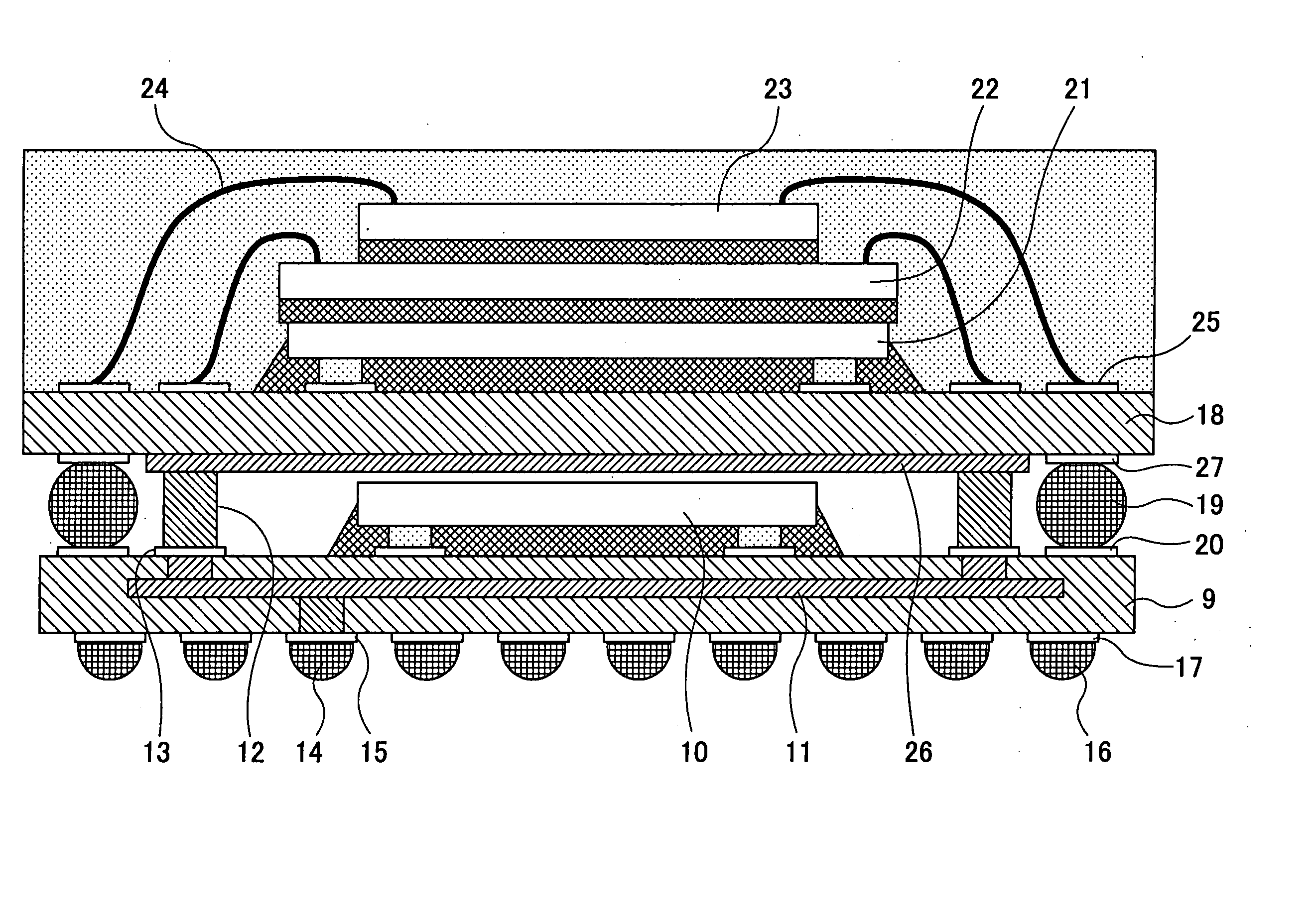
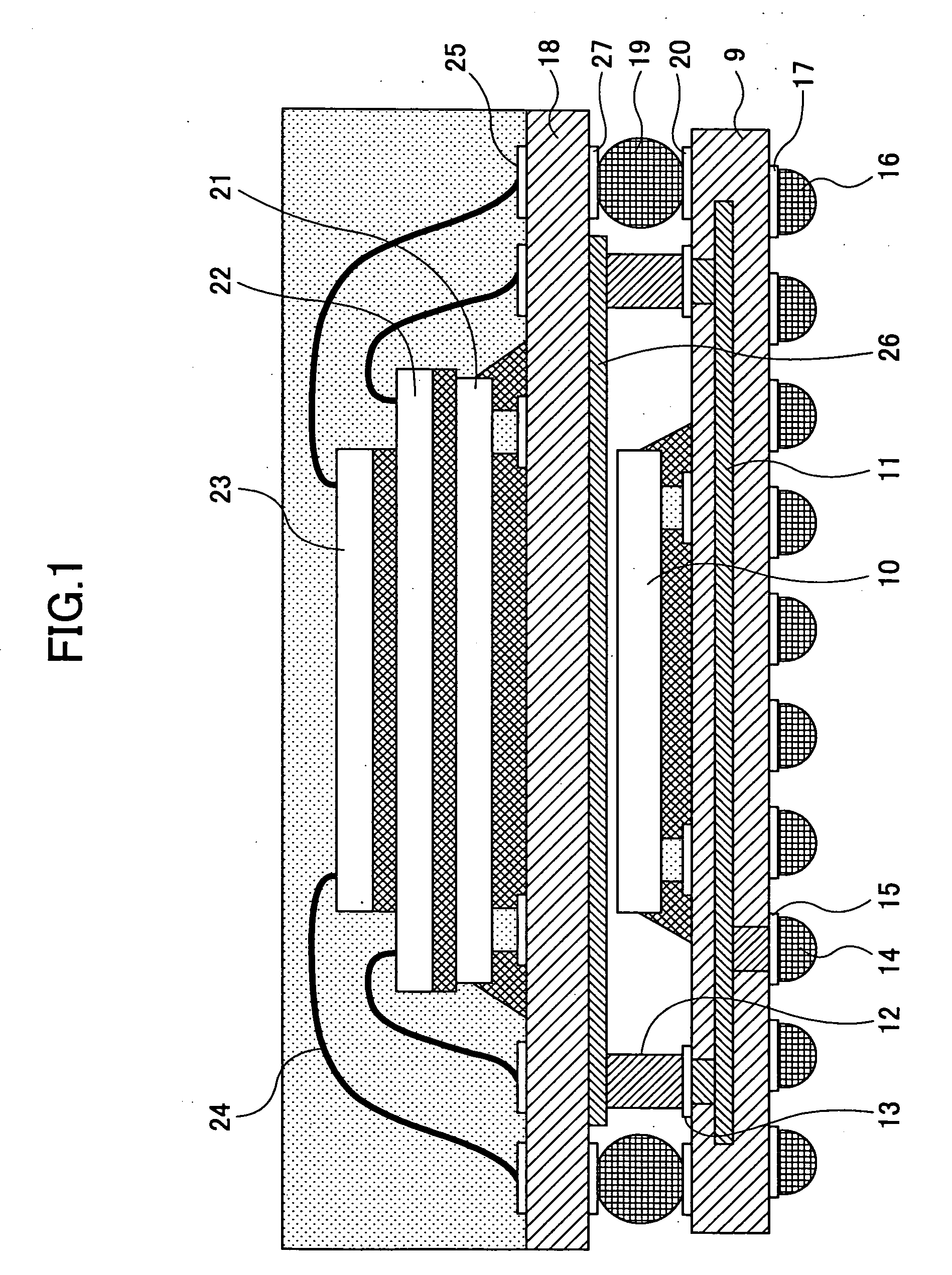
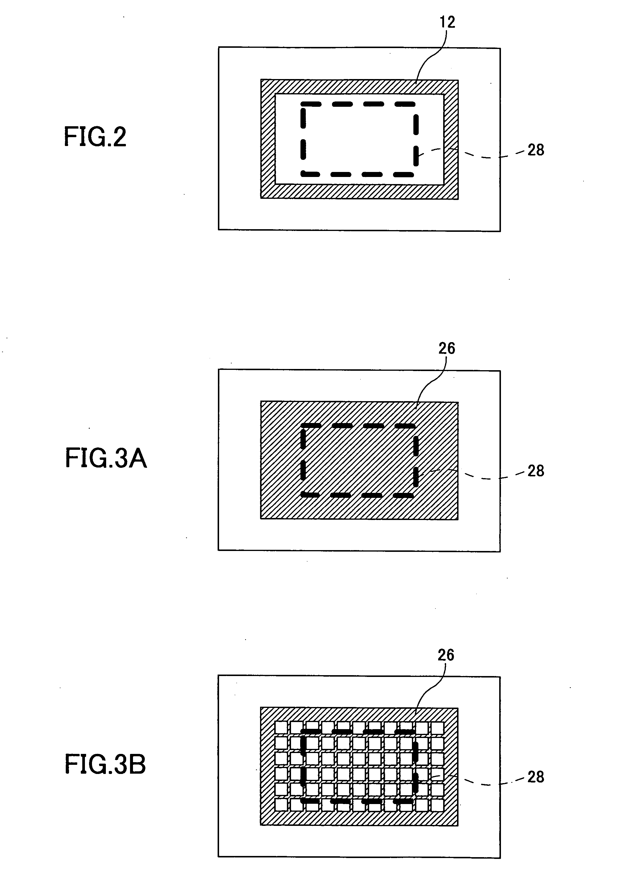
[0022]FIG. 1 shows a side elevational sectional view of a stacked-type semiconductor device in the present invention; FIG. 2 shows a plan view illustrating a structure of a conductor supporting member 12 in the stacked-type semiconductor device shown in FIG. 1; and FIGS. 3A and 3B show plan view respectively illustrating alternative examples of a pattern of a ground wiring layer 26 in the stacked-type semiconductor device shown in FIG. 1. As shown in the figures, the stacked-type semiconductor device includes wiring substrates 9 and 18; ground wiring layers 11 and 26; the conductor supporting member 12; connecting pads 13, 15, 17, 20, 25 and 27; semiconductor device elements 10, 21, 22 and 23; and wires 24.
[0023] In the stacked-type semiconductor device in the first embodiment of the present invention, the wiring substrate 9 is made of a material such as a glass epoxy resin, ceramics or such; the semiconductor device element 10 is mounted on the top side of the wiring substrate 9 in...
second embodiment
[0028]FIG. 4 shows a side elevational sectional view of a stacked-type semiconductor device in the present invention.
[0029] The second embodiment is different from the above-described first embodiment in that a ground wiring layer 30 in a top-side wiring substrate 29 is embedded inside of the wiring substrate 29. Other than this point, the second embodiment is same as the first embodiment in configuration. Accordingly, the stacked-type semiconductor device according to the second embodiment provides advantages same as those provided by the stacked-type semiconductor device according to the first embodiment. Furthermore, in the stacked-type semiconductor device according to the second embodiment, since the ground wiring layer 30 is embedded inside of the wiring substrate 29, it is possible to position the ground wiring layer 30 closer to the semiconductor device elements 21, 22 and 23 which are mounted on the top side of the wiring substrate 29 accordingly. Thereby, it is possible to...
fourth embodiment
[0031]FIG. 7 shows a side elevational sectional view of a stacked-type semiconductor device in the present invention.
[0032] In the fourth embodiment, high-heat-conductive adhesive 32 such as resin adhesive including silver powder, for example, is filled with between the top side of the semiconductor device element 10 mounted on the wiring substrate 9 and the ground wiring layer 26 formed on the bottom side of the wiring substrate 18 in the above-described third embodiment. In the stacked-type semiconductor device according to the fourth embodiment, a path is created by the high-heat-conductive adhesive 32 for transmitting heat generated from the top surface of the semiconductor device element 10 through the ground wiring layer 26 and the solder balls used as the conductor supporting members 31. Thereby it is possible to improve the heat radiation performance of the semiconductor device element 10.
PUM
 Abstract
Description
Claims
Application Information
 - R&D
- Intellectual Property
- Life Sciences
- Materials
- Tech Scout
- Unparalleled Data Quality
- Higher Quality Content
- 60% Fewer Hallucinations
Browse by: Latest US Patents, China's latest patents, Technical Efficacy Thesaurus, Application Domain, Technology Topic, Popular Technical Reports.
© 2025 PatSnap. All rights reserved.Legal|Privacy policy|Modern Slavery Act Transparency Statement|Sitemap|About US| Contact US: help@patsnap.com


