Brightness and contrast enhancement of direct view emissive displays
a technology of emissive display and brightness, which is applied in the direction of luminescnet screen, discharge tube, instruments, etc., can solve the problems of limiting the ability to readily increase brightness, heavy draining of battery power, and increasing the light output of light sources, so as to increase the brightness of emissive devices, increase the amount of light, and increase the power supply
- Summary
- Abstract
- Description
- Claims
- Application Information
AI Technical Summary
Benefits of technology
Problems solved by technology
Method used
Image
Examples
example 1
Volume Diffuser
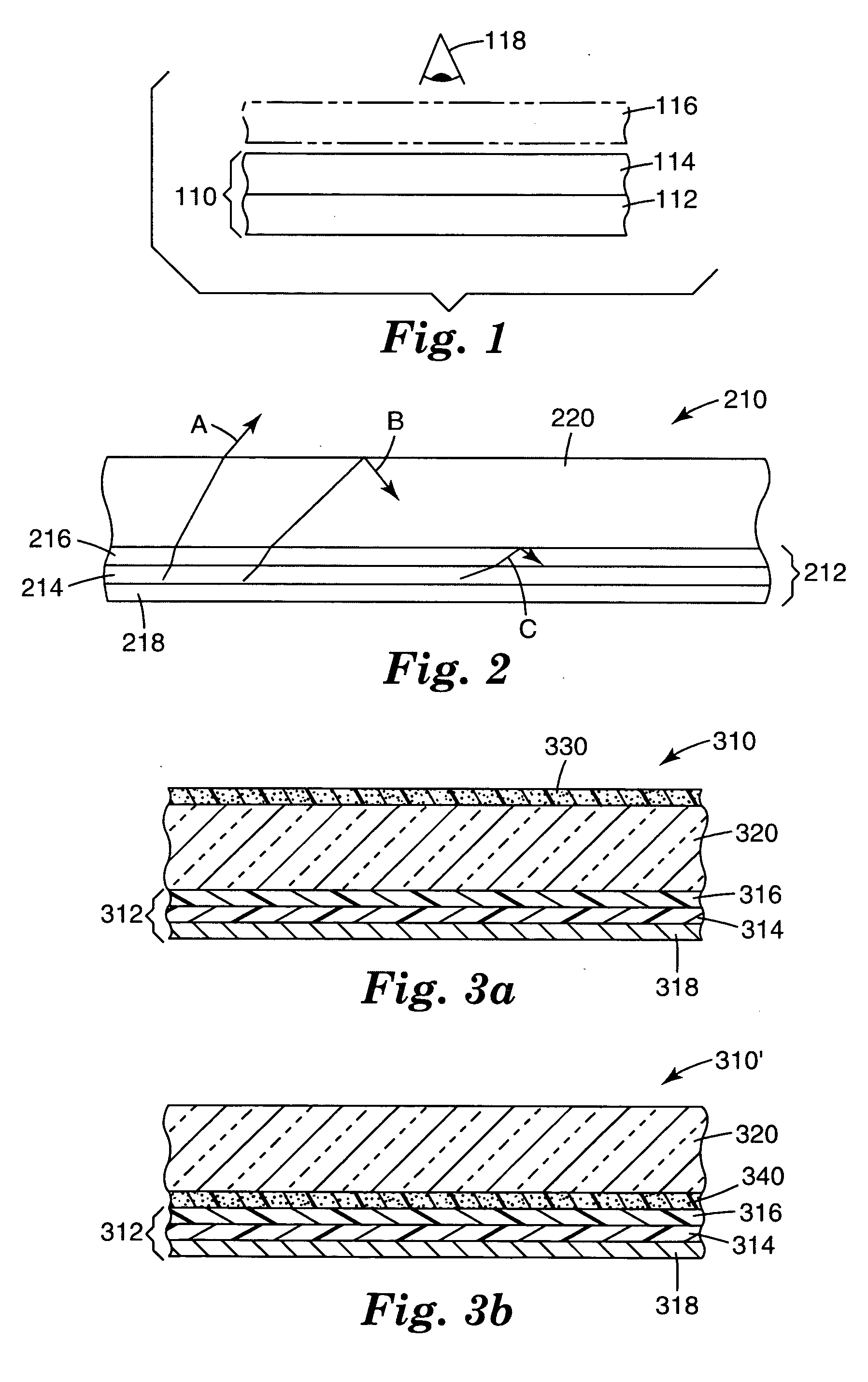
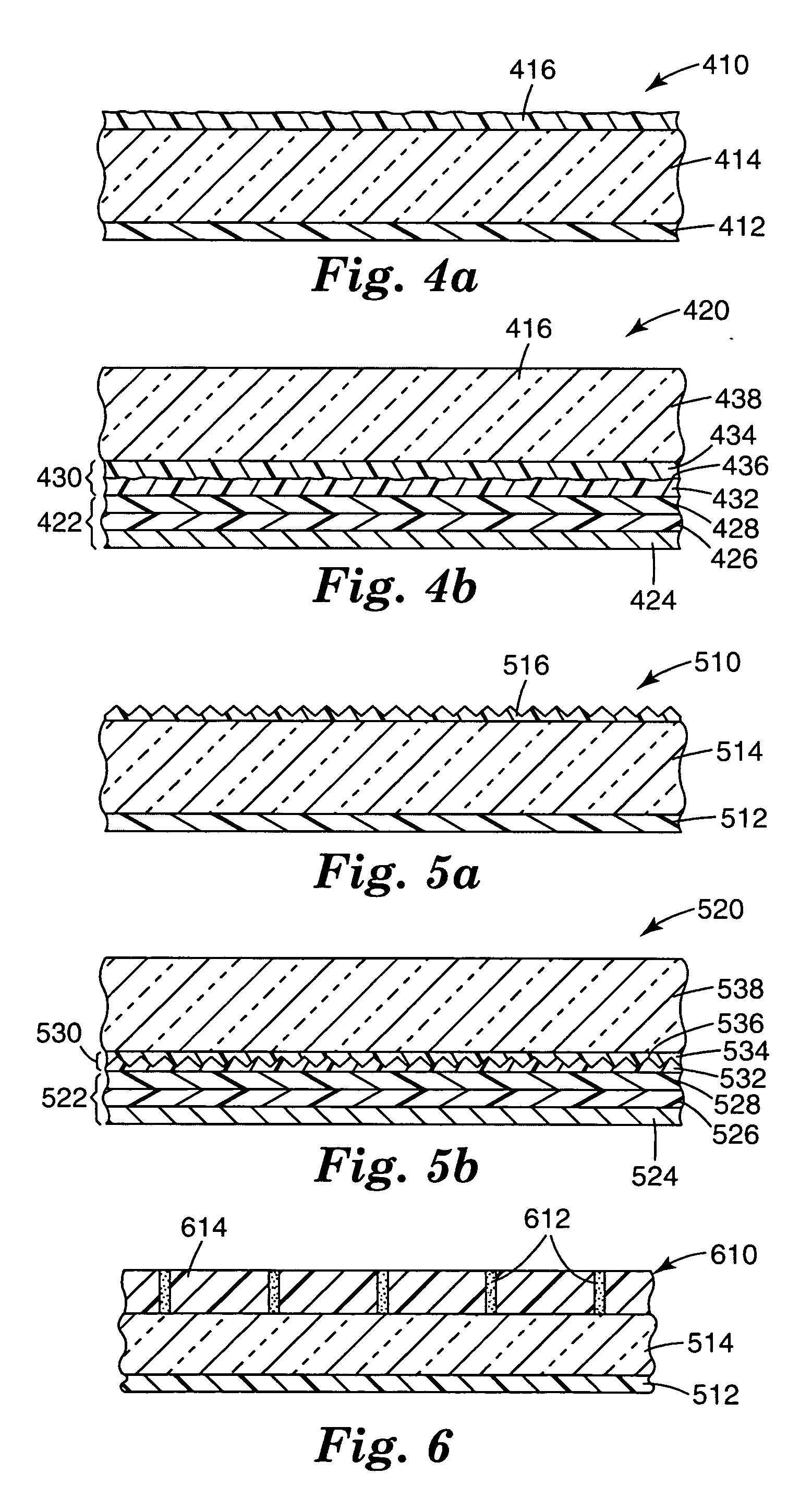
[0063] In this example, the gain associated with volume diffusers laminated between the dyed PVC film and the PET substrate was measured as a function of scatterer loading. The volume diffusers were made by dispersing various amounts of Sb2O3 particles (refractive index=2.1, average diameter=3 microns) in a thermoplastic PET material (refractive index=1.56) to make mixtures, and coating the mixtures onto the PET substrate using a #20 Meyer bar. The coatings were then dried to form constructions that consisted of volume diffusers bonded to PET substrates. The volume diffusers each had thicknesses of about 4 microns. For each construction, the volume diffuser side was thermally laminated to a dyed PVC film at about 300° F. The resulting samples had, in the following order, a dyed PVC film, a 4 micron thick volume diffuser, and a PET substrate. Each sample was placed on the uv light source and gain was measured as a function of angle. Table 1 reports the gain at normal ...
example 2
Volume Diffuser
[0066] In this example, gain was measured for volume diffuser TIR frustrators as a function of refractive index of a lamination adhesive disposed between the volume diffuser and the dyed PVC film. Volume diffusers were made by dispersing Sb2O3 particles in thermoplastic PET (40 wt. % particles to PET) and then coating the mixture onto the PET substrate. The volume diffusers had a thickness of about 4 microns. The volume diffusers were then laminated to the dyed PVC films using various adhesives. The type of adhesive, the refractive index of the adhesive, and the measured gain for each of the samples are reported in Table 2.
TABLE 2Gain as a function of laminating adhesive refractive indexRefractiveAdhesiveIndexGainLow index pressure adhesive1.47512.57High index pressure adhesive1.54473.02PET thermoplastic1.55672.76
[0067] Table 2 indicates that the closer the refractive index of the adhesive was to the refractive index of the dyed PVC film, the higher the observed ga...
example 3
Volume Diffuser
[0068] In this example, gain was measured for volume diffuser TIR frustrators as a function of the refractive index of a lamination adhesive disposed between the volume diffuser and a glass substrate. The same volume diffusers were made as described in Example 2 (i.e., particles dispersed in thermoplastic PET and coated onto PET substrate). The coated side of the volume diffuser was laminated to a 1 mm thick glass substrate using the various adhesives reported in Table 3. The dyed PVC film was laminated to the other side of the glass substrate using an optically clear adhesive commercially available from Minnesota Mining and Manufacturing under the trade designation 3 M Laminating Adhesive 8141(index of refraction=1.475). The gain for each construction is reported in Table 3.
TABLE 3Gain as a function of laminating adhesive refractive indexRefractiveΔn (glass andAdhesiveIndexadhesive)GainNone (bare glass)1.5115—1Adhesive 11.47510.03642.71Adhesive 21.50390.00762.91Ad...
PUM
 Abstract
Description
Claims
Application Information
 - R&D
- Intellectual Property
- Life Sciences
- Materials
- Tech Scout
- Unparalleled Data Quality
- Higher Quality Content
- 60% Fewer Hallucinations
Browse by: Latest US Patents, China's latest patents, Technical Efficacy Thesaurus, Application Domain, Technology Topic, Popular Technical Reports.
© 2025 PatSnap. All rights reserved.Legal|Privacy policy|Modern Slavery Act Transparency Statement|Sitemap|About US| Contact US: help@patsnap.com


