

Discharge power supply apparatus
- Summary
- Abstract
- Description
- Claims
- Application Information
AI Technical Summary
Benefits of technology
Problems solved by technology
Method used
Image

Examples
first embodiment
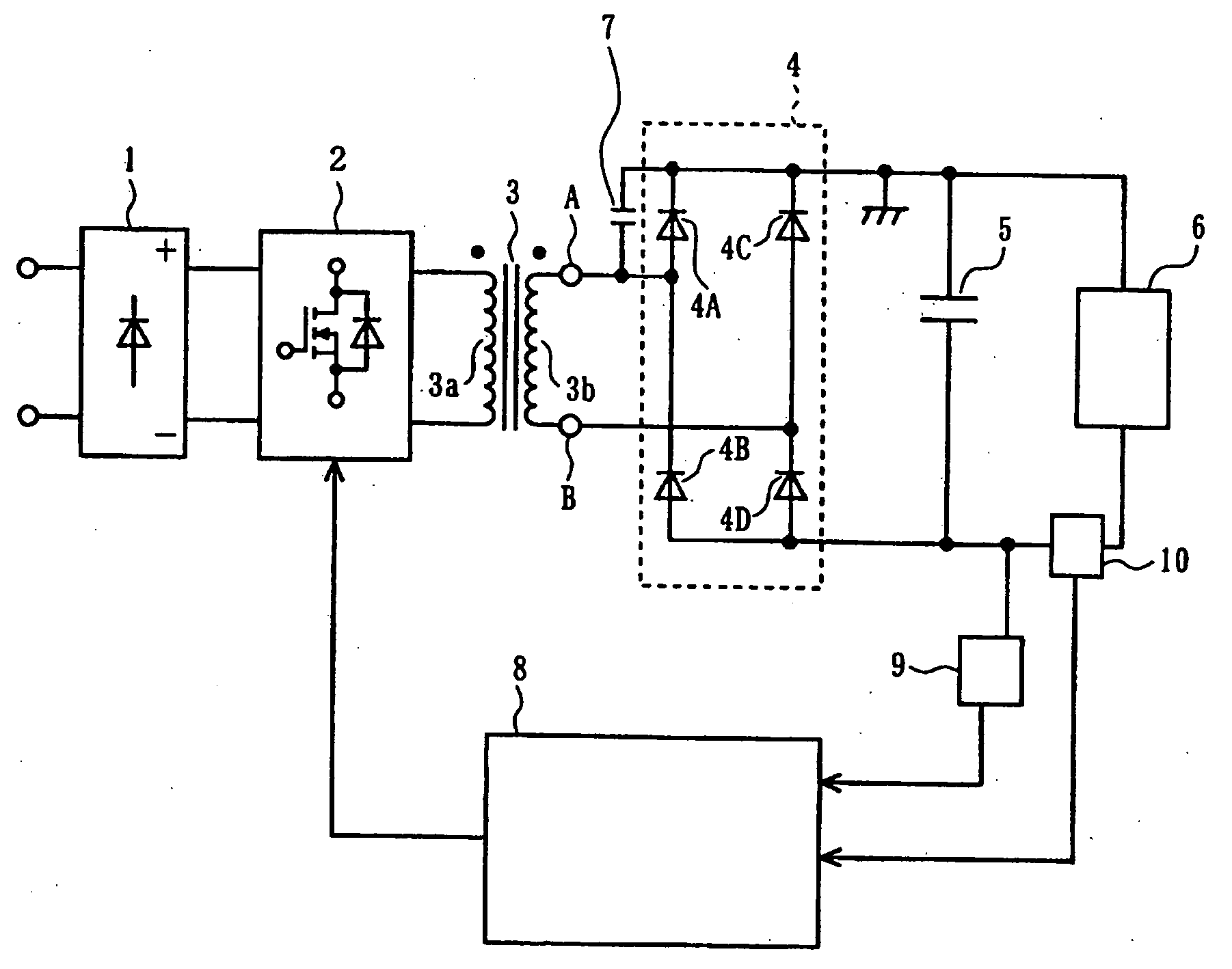
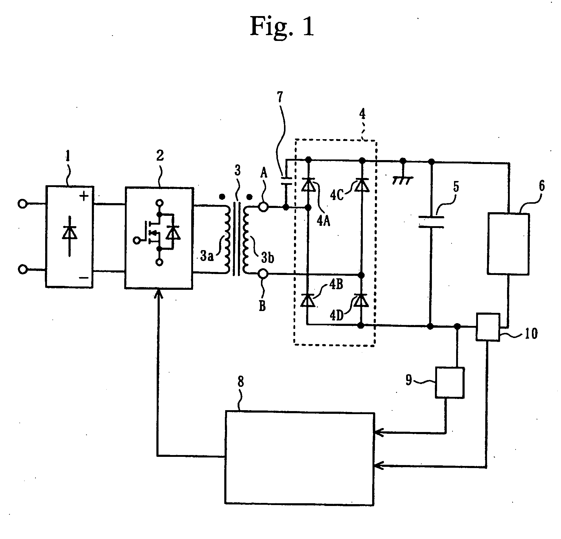
FIG. 1 is a circuit diagram showing the discharge power supply apparatus of the present invention, and FIGS. 2A to 2C are circuit diagrams for explaining the operation thereof. The input side rectifier circuit 1 converts a single-phase alternating current voltage to direct current voltage by rectification, and the inverter circuit 2 converts this direct current voltage to a high frequency alternating current voltage of, for example, several kHz to several 10 kHz. The alternating current input in this example is a single-phase alternating current, but can be an alternating current having three or more phases. In this case, the rectifier 1 can be a bridge rectifier having three or more phases. The inverter circuit 2 carries out, for example, pulse width control (ON time ratio control). However, the inverter circuit 2 can be an inverter circuit that carries out control other than pulse width control, such as frequency modulation control or the like.
In the transformer 3, the high frequ...
second embodiment
FIG. 4 shows the present invention. In FIG. 1, a full-bridge rectifier circuit is used as a full-wave rectifier circuit 4, whereas in this embodiment, a center tapped rectifier circuit is used. In FIG. 4, elements that are identical to those in FIG. 1 are denoted by identical reference symbols and their explanation is omitted.
The transformer 3 provides a secondary winding 3b and a secondary winding 3c connected serially. Between the secondary windings 3b and 3c, a center point 3d is provided as the center tap. The terminals A and B of the secondary windings 3b and 3c are respectively serially connected to the diodes 4A and 4B, and thereby a center tap full-wave rectifier circuit 4 is formed. The full-wave rectifier circuit 4 carries out operations that are identical to the first embodiment.
One diode 4A and the trigger capacitor 7 are connected in parallel. Instead of the diode 4A, the diode 4B and the trigger capacitor 7 can be connected in parallel. If the voltages generated by ...
third embodiment
FIG. 5 shows the present invention. In FIG. 1, a portion of the diodes, which are bridge connected to form the full-wave rectifier circuit 4, is connected to the trigger capacitor 7. In contrast, as shown in FIG. 5, in this discharge power supply apparatus, among the two rows of diodes that form the bridge circuit of the full-wave rectifier circuit 4, the diodes 4A and 4B, connected serially, are respectively connected to the trigger capacitors 7 and 7′. In FIG. 5, the elements identical to those in FIG. 1 are denoted by identical reference symbols, and their explanation is omitted.
The operation of this discharge power supply apparatus will be explained. During the half-cycle when a positive bias is applied to the terminal B and a negative bias is applied to the terminal A, the high frequency alternating current voltage E of the secondary winding 3b charges the trigger capacitor 7 by passing through the diode 4C from the terminal B. Next, during the half-cycle when a positive bias ...
PUM
 Abstract
Description
Claims
Application Information