

Microlens device and method of manufacturing the same, electro-optic device and electronic apparatus
a micro-lens and manufacturing method technology, applied in the field of micro-lens devices and their manufacturing methods, electro-optic devices, electronic devices, etc., can solve problems such as contrast drops
- Summary
- Abstract
- Description
- Claims
- Application Information
AI Technical Summary
Benefits of technology
Problems solved by technology
Method used
Image

Examples
first exemplary embodiment
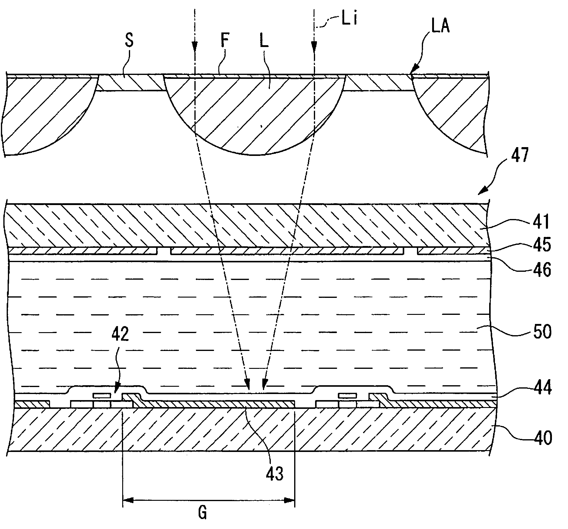
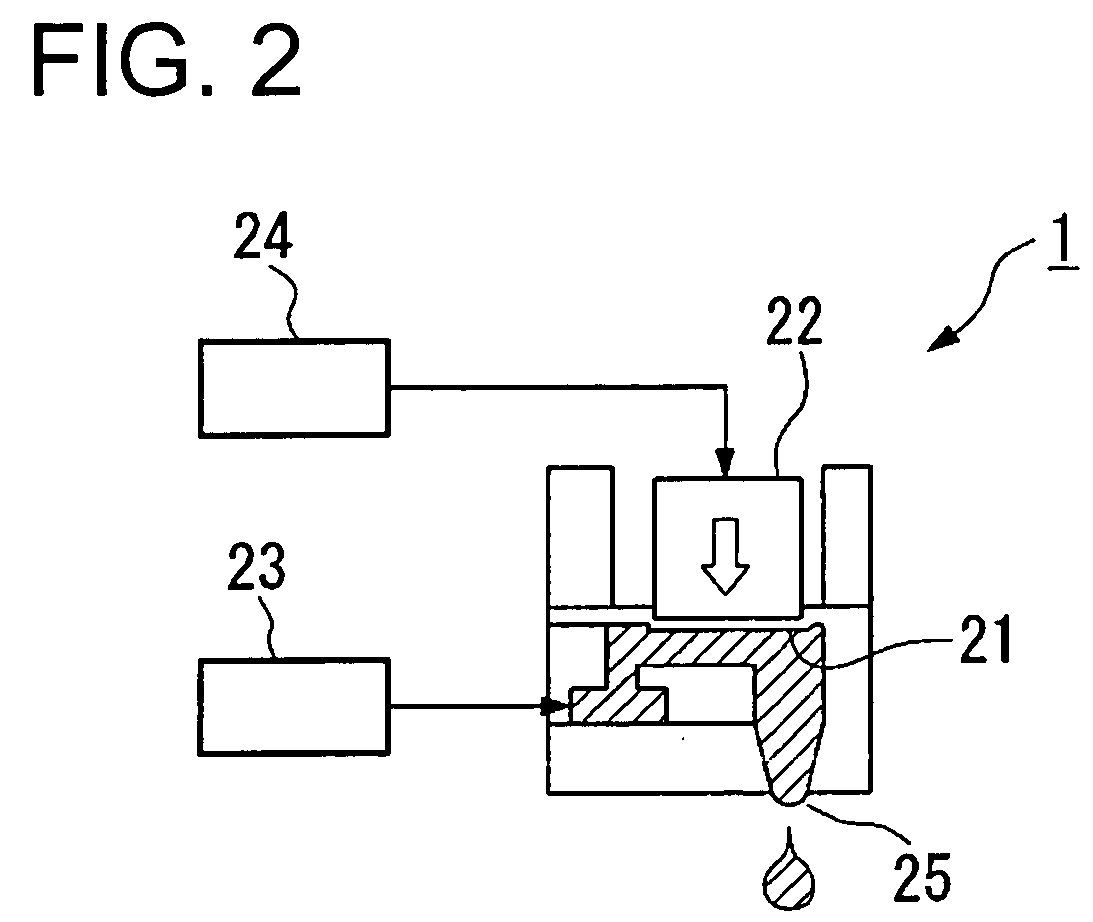
The present exemplary embodiment is described using an example in which translucent resin is ejected as a droplet from a nozzle of a droplet ejection head by a droplet ejection method and is applied to a translucent substrate to form a lens section and then light blocking (lightproof) ink is ejected as a droplet to apply to the gap between the lens sections.
If the microlens to be manufactured is applied as, for example, an optical membrane for a screen, a translucent sheet or a translucent film is used as a substrate, the translucent sheet or the translucent film including cellulosic resin, such as acetylcellulose or propyl cellulose, or transparent resin (translucent resin), such as polyvinylchloride, polyethylene, polypropylene, or polyester. Furthermore, if the microlens is applied as a microlens array, a substrate made of a transparent material (a translucent material), such as glass, polycarbonate, polyarylate, polyethersulfone, amorphous polyolefin, polyethylene terephthala...
second exemplary embodiment
The first exemplary embodiment described above has a configuration of blocking the light entering the gap S between the lens sections L. However, it is also effective to reduce the view angle dependency to use a material that does not block the whole light but transmits a part of the light. Other than the configuration of blocking at least a part of the light, it is also possible to adopt a configuration in which the incident light is emitted after being scattered by a scattering material contained in the ink. Thereby the rectilinear propagation of the incident light is controlled. In this case, although almost the whole light passing through the gap S is output, it is still possible to contribute to broadening the view angle because the output light is scattered.
As a configuration of scattering light, it is also possible to use the same UV-curing resin as the lens sections L instead of using the ink containing the scattering material.
Specifically, by adjusting the contact angl...
third exemplary embodiment
FIG. 5 shows a cross-sectional schematic of the microlens having a double layer structure.
As shown in this figure, by similar processes to the first exemplary embodiment described above, the lens sections L and the light-blocking section S1 defined between the lens sections L are first formed on the substrate P as a first layer. Then a covering layer H for covering the above is formed. Taking the above process to apply lyophilicity (the UV-curing process) and translucency into consideration, ceramics materials, such as silicon nitride (Si3N4) or silicon oxide (SiO2) can be used as the covering layer H.
Then, a second layer of the microlens array is formed on the covering layer H that functions as a substrate in the same manner as the first layer. In this case, the microlens arrays are arranged so that the lens sections L of one layer are shifted from those of the other layer. Preferably, as shown in the drawing, they are arranged so that the pitch of the lens sections L of the fi...
PUM
 Abstract
Description
Claims
Application Information