
Nonvolatile memory

a non-volatile memory and memory technology, applied in the field of non-volatile memory, can solve the problems of reducing unable to recognize the memory, and unable to operate normally in the system, so as to reduce the load on the system developer

Inactive Publication Date: 2005-01-13
RENESAS ELECTRONICS CORP
View PDF6 Cites 4 Cited by
  • Summary
  • Abstract
  • Description
  • Claims
  • Application Information

AI Technical Summary

Benefits of technology

[0006] However, a conventional flash memory is usually designed to undergo rewriting of management table information for managing defective addresses and other such functions by an external controller. Moreover, since the reliability of data in a flash memory is less than that of data in a mask ROM or RAM because of threshold voltage fluctuations in memory cells and their aging, in configuring a system using any flash memory the reliability of data is increased by equipping the external controller with an error checking and correcting function known as ECC. For this reason, a conventional flash memory imposes a greater load on the system developer when a new system using any flash memory is to be developed.
[0008] An object of the present invention is to make it possible to reduce the load on the system developer by using a nonvolatile memory which permits electrical writing and erasion of information to be stored, such as a flash memory.
[0009] Another object of the invention is to make it possible, in a nonvolatile memory which permits electrical writing and erasion of information to be stored, such as a flash memory, to prevent the system using it from running into an abnormal state in which the system becomes unable, and enable the system to operate even if important data for the system, such as management and address translation information, are damaged.
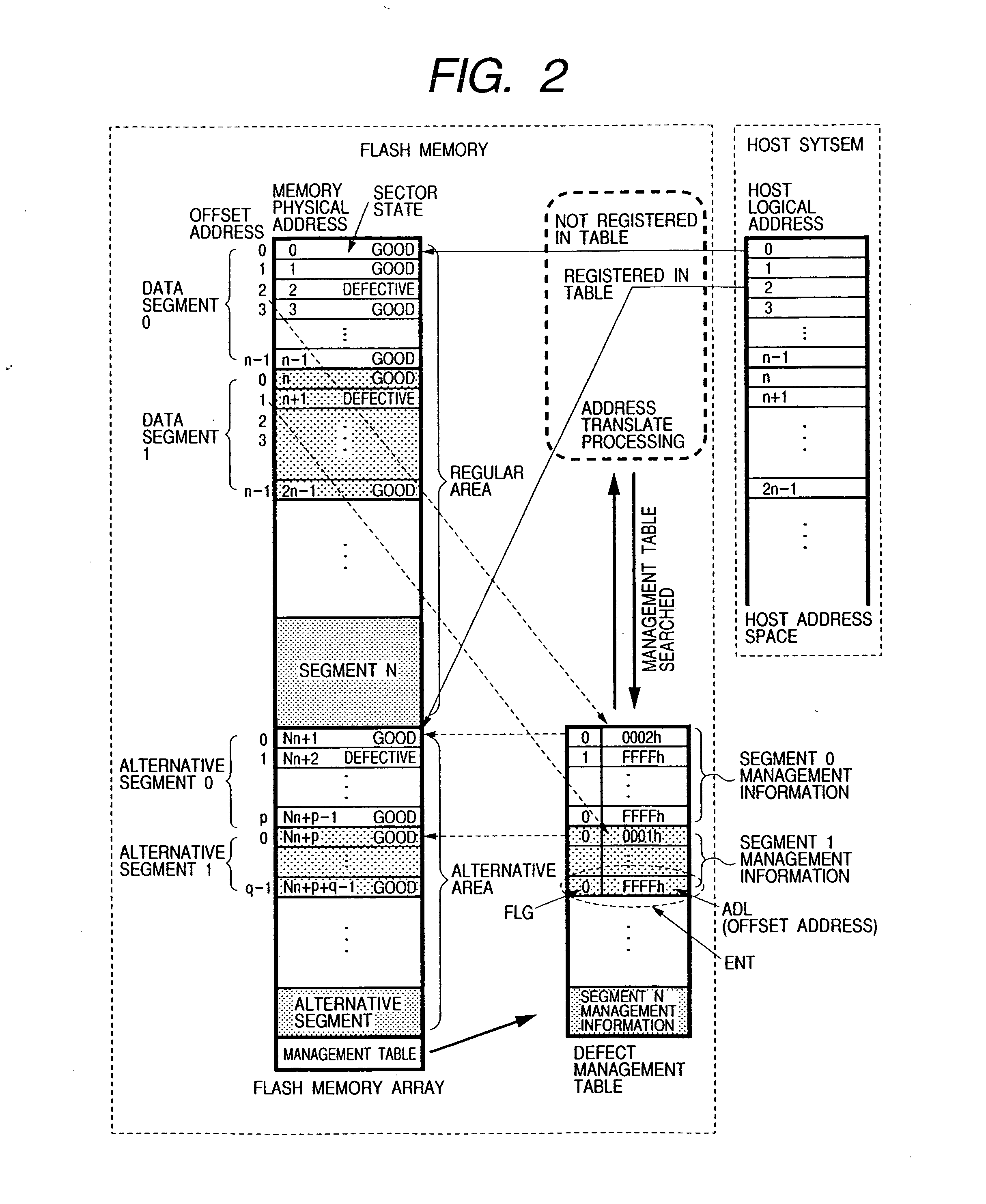
[0013] As the nonvolatile memory described above has a replacing function and an error correcting function, there is no need- to cause an external controller to process replacement or error correction, it is made possible to reduce the load on the system developer and, since a plurality of sets of address translation information are stored, it is further made possible to avoid, even if any set of address translation information is lost, an abnormal state in which the system becomes unable to operate by having another set of such information substituted for the lost information.
[0014] Preferably, the memory array should be provided with two or more areas which do not affect each other even if power supply is interrupted during the process of writing into or erasing data in any of the memory cell groups, and the plural sets of first address translation information and second address translation information be stored successively in the two or more second areas. This makes it possible to prevent, even if data in any area in which address translation information is to be stored are lost as a result of writing or erasion, such information stored in other areas from being lost, and to avoid without fail an abnormal state in which the system becomes unable to operate.

Problems solved by technology

For this reason, a conventional flash memory imposes a greater load on the system developer when a new system using any flash memory is to be developed.
A conventional flash memory involves another problem that, where a storage area containing any defective memory cell is used as a system area for storing important data for the system, such as table data for managing file positions on the memory, format information and address translation information, it may become impossible to recognize the memory or for the system to operate normally.

Method used


Image

  • Nonvolatile memory
  • Nonvolatile memory
  • Nonvolatile memory

Examples


Embodiment Construction

[0044] One preferred embodiment of the present invention will be described in detail below with reference to the accompanying drawings.

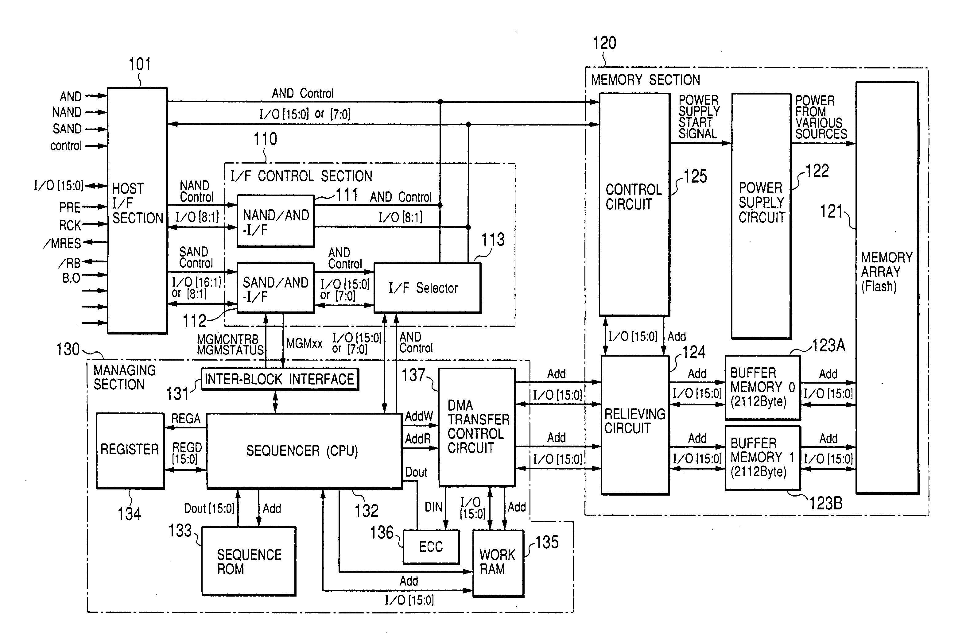
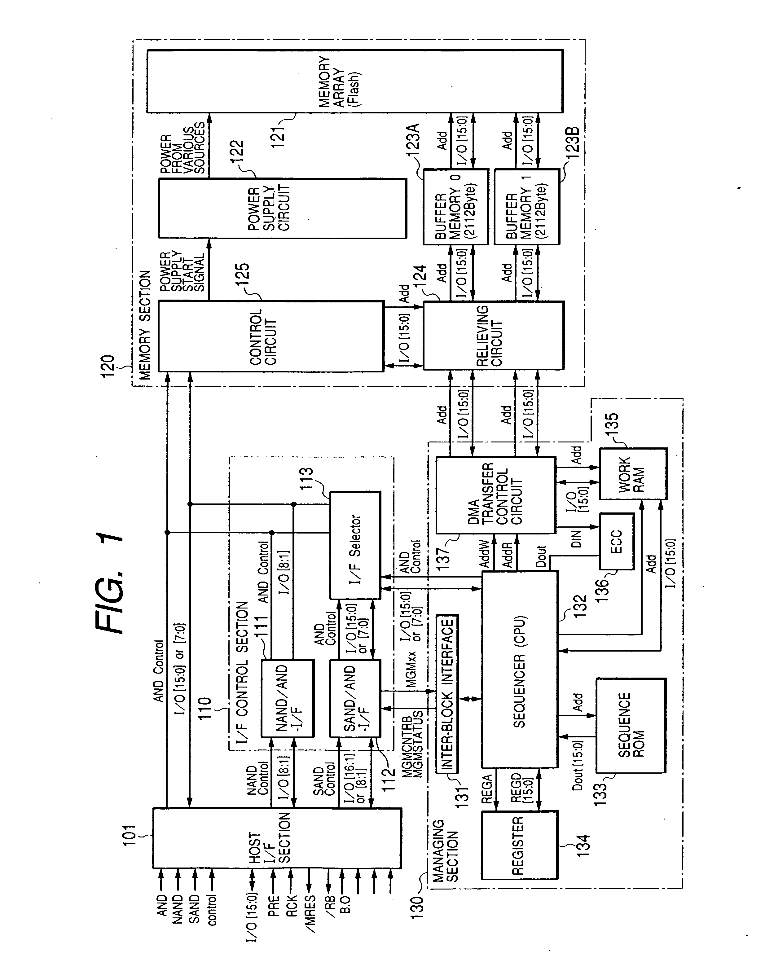
[0045]FIG. 1 is a block diagram illustrating an embodiment of flash memory as an example of nonvolatile memory to which the present invention can be effectively applied. The flash memory of this embodiment is composed of a host interface section 101 to perform inputting and outputting of signals to and from a controller, such as an external host CPU, an interface control section 110 to control the host interface section 101, a memory section 120 consisting of a flash memory array 121 in which a plurality of nonvolatile memory elements (memory cells) are arranged in a matrix and its peripheral circuits, and a managing section 130 to manage defective addresses and the like. These elements are formed over a single semiconductor chip, such as a monocrystalline silicon chip.

[0046] Whereas conventional flash memories include a plurality of kinds of chips...


PUM


Abstract

For a nonvolatile memory permitting electrical writing and erasing of information to be stored, such as a flash memory, the load on the system developer is to be reduced, and it is to be made possible to avoid, even if such important data for the system as management and address translation information are damaged, an abnormal state in which the system becomes unable to operate. The nonvolatile memory is provided with a replacing function to replace a group of memory cells including defective memory cells which are incapable of normal writing or erasion with a group of memory cells including no defective memory cell, a numbers of rewrites averaging function to grasp the number of data rewrites in each group of memory cells and to so perform replacement of memory cell groups that there may arise no substantial difference in the number of rewrites among a plurality of memory cell groups, and an error correcting function to detect and correct any error in data stored in the memory array, wherein first address translation information deriving from the replacing function and second address translation information deriving from the numbers of rewrites averaging function are stored in respectively prescribed areas in the memory array, and the first address translation information and second address translation information concerning the same memory cell group are stored in a plurality of sets in a time series.

Description

CROSS-REFERENCE TO RELATED APPLICATION [0001] This application is a continuation of application Ser. No. 10 / 667,505 filed Sep. 23, 2003.BACKGROUND OF THE INVENTION [0002] The present invention relates to a nonvolatile memory which permits electrical writing and erasion of information to be stored, and to a technique that can be effectively applied to a flash memory provided with a replacing function to any defective area in memory array and having an area in which to store a management information table for managing defective addresses. [0003] A flash memory uses as its memory cells nonvolatile memory elements each consisting of a double gate-structured MOSFET having a control gate and a floating gate, and is caused to store information by varying the accumulated charge of the floating gate and thereby varying the threshold voltage of the MOSFET. [0004] In a flash memory, the threshold voltage is varied when data are to be written into memory cells or data therein are to be erased, ...

Claims


Application Information

Patent Timeline
Patent Type & Authority Applications(United States)
IPC IPC(8): G06F12/16G06F12/02G11C16/02G11C16/06G11C16/34G11C29/00G11C29/42
CPCG06F11/1068G06F12/0246G06F12/06G06F2212/1036G11C2029/0409G11C16/10G11C16/349G11C29/44G11C29/76G11C16/04
Inventor KOZAKAI, KENJINAKAMURA, TAKESHIISHII, TATSUYATSUNODA, MOTOYASUIGUCHI, SHINYAMARUYAMA, JUNICHI
Owner RENESAS ELECTRONICS CORP
Learn More