Csf physiologic controller

a physiologic controller and controller technology, applied in the field of physiologic controllers, can solve the problems of unbalanced fluid system, serious complications, and fluid not being removed quickly,

Inactive Publication Date: 2005-01-13
KUCHTA JOHN
View PDF9 Cites 43 Cited by
  • Summary
  • Abstract
  • Description
  • Claims
  • Application Information

AI Technical Summary

Benefits of technology

[0020] The limitations of the current shunt therapy for hydrocephalus have been overcome by the present invention. The CSF Physiologic Controller is an implantable active battery-operated device that is microprocessor controlled via algorithms stored in its memory. It is a multi-mode drainage system that contains at least two flow paths: a low resistance flow path for when the patient is in the supine or substantially supine position and a flow path containing a programmable variable check valve to prevent over-drainage when the patient is in the upright or substantially upright position. The Controller also contains numerous diagnostic features, which enable the physician to monitor the operation of the system, as well as several key patient parameters non-invasively.

Problems solved by technology

This fluid system becomes unbalanced when the rate of CSF production in the ventricles is greater than the rate of CSF absorption into the bloodstream.
A high level of pressure for any sustained period can lead to serious complications.
Under-drainage, in which the fluid is not removed quickly enough, is a common problem of the shunt system.
This breakage or disconnection disrupts the new path made for the CSF and causes increased pressure in the ventricles.
Rapid increase in IVP may result in loss of consciousness, and emergency treatment is required.
Headaches increase in frequency and severity, often worse upon waking in the morning.
Over-drainage, in which the shunt allows CSF to drain from the ventricles more quickly than it is being produced, is also a common problem in shunt therapy.
If this happens suddenly, such as soon after the shunt is inserted, then the ventricles of the brain may collapse, tearing delicate blood vessels on the outside of the brain and causing a hemorrhage.
This can be trivial or it can cause symptoms similar to those of a stroke.
The blood may have to be removed, and in some cases, if this is not done, it may be the cause of epilepsy later.
This often interferes with the function of the shunt, causing the opposite problem, high IVP.
Unfortunately, the slit ventricles may not always increase is size, resulting in headache and vomiting.
With over-drainage, headaches often become worse getting up from a supine (horizontal) position.
This is because the change in position causes excessive drainage to occur, since gravity forces more CSF to drain.
With under-drainage, headaches caused by high IVP often become worse on waking in a supine position.
Current shunt therapy devices are not designed to effectively treat over-drainage.
A change of valve to a higher pressure cannot be relied upon to cure it, though it appears to do so in some cases.
Anti-siphon devices, which consist of a small button inserted into the shunt tubing, may sometimes solve the problem.
This is useful where the need for a valve of a different pressure arises, but the adjustable valve is no less prone to the over-drainage issue than any other and it cannot be used to treat this condition.
The name of this condition is misleading, however, because some patients have fluctuations of IVP from high to normal to low.
In the former, the problem is usually failure to absorb the CSF at the end of the system, whereas in the latter, there is blockage of the CSF pathways within the ventricular system.
Short-term changes, such as when the patient rises from a horizontal position to a standing position, may cause excess drainage because of the added siphoning of the vertical tubing.
In the longer term, passive check valves are not able to automatically maintain normal IVP by adjusting CSF drainage if the patient experiences changes in CSF generation.
Note that the selection of a pressure valve may result in a compromise between under-drainage in the supine position and over-drainage in the upright position.
The current shunt systems have no method for non-invasively measuring the CSF drained flow rate.
Therefore, once installed, it is difficult to monitor the shunt's operation.
Sustained low or high IVP may lead to serious complications.
The current shunt systems do not have the capability to monitor, store, and transmit data related to CSF flow, IVP or cannula operation.

Method used


Image

  • Csf physiologic controller
  • Csf physiologic controller
  • Csf physiologic controller

Examples


Embodiment Construction

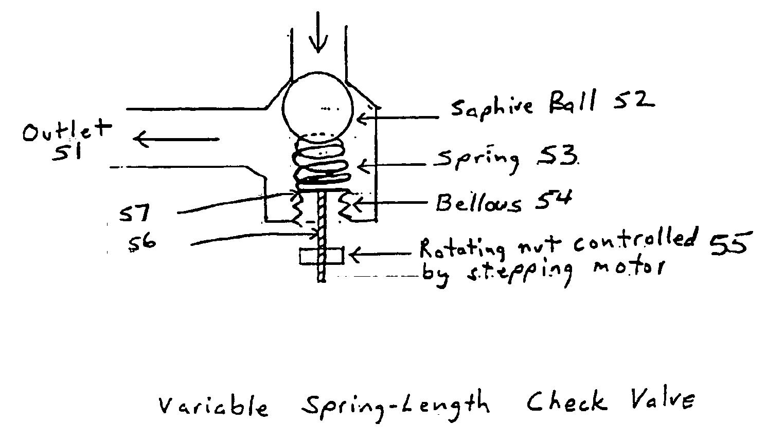
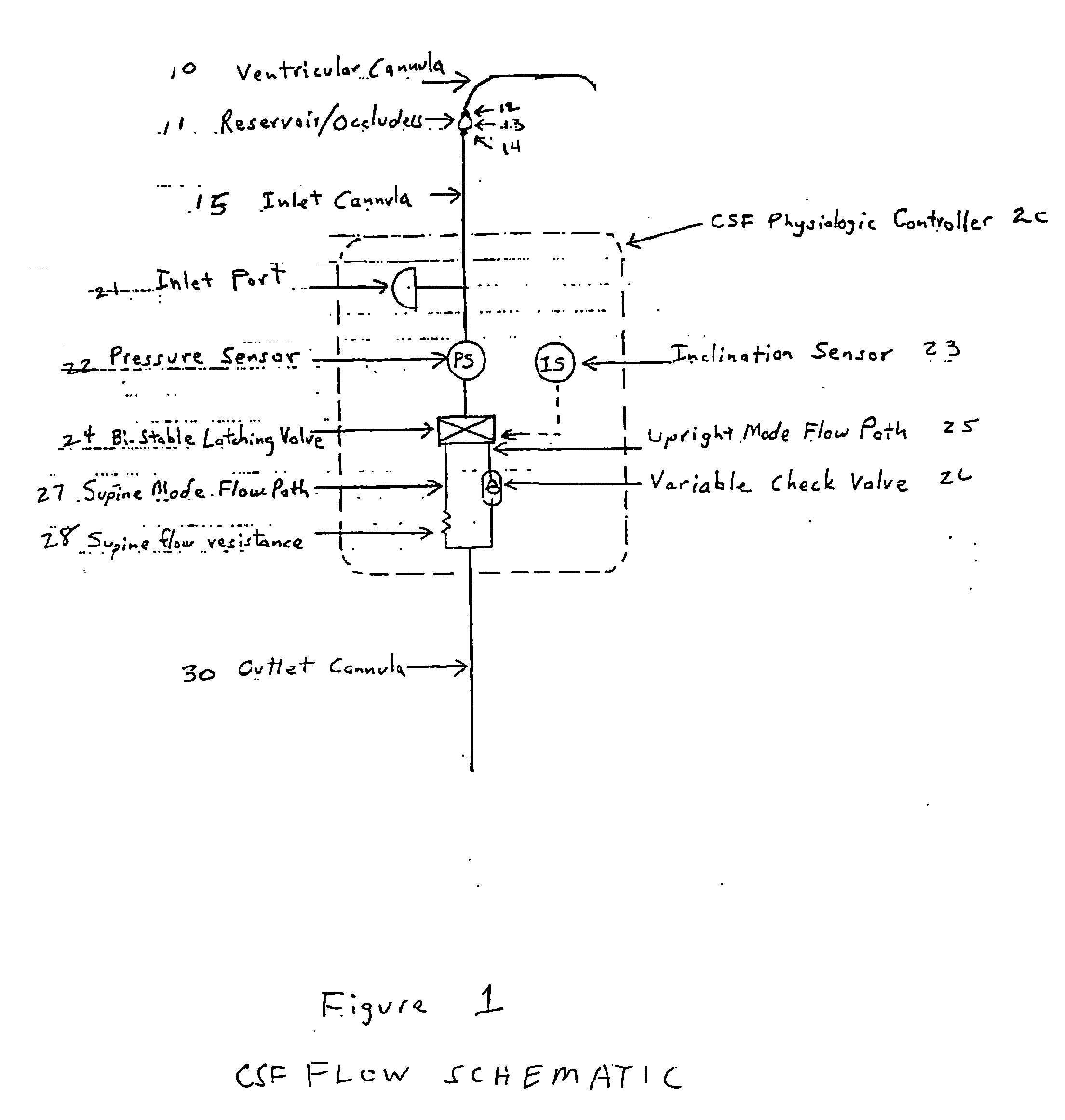
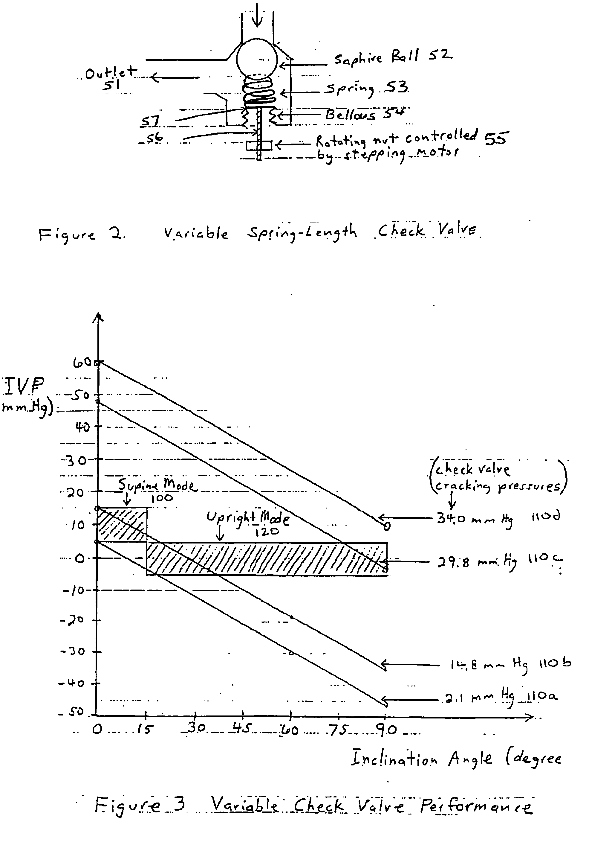
[0027] The CSF Physiologic Controller is a multi mode drainage system that contains at least two flow paths: (1) a supine mode: a low resistance flow path for when the patient is in the supine or substantially supine position and (2) an upright mode: a flow path containing a programmable variable check valve to prevent over-drainage when the patient is in the upright or substantially upright position. A bi-stable latching valve directs the CSF flow to either the low resistance path or the check valve path based on an inclination sensor within the CSF Physiologic Controller. If the inclination sensor angle is below a programmable critical angle, the bi-stable latching valve directs flow to the low resistance path. If the inclination sensor angle is equal to or above a critical programmable angle, the bi-stable latching valve directs flow to the check valve path. For purposes of illustration, a dual mode controller will be described; however, the present invention is not limited to on...


PUM


Abstract

The Cerebrospinal Fluid (CSF) Physiologic Controller is an implantable active battery-operated device that is microprocessor controlled via algorithms stored in its memory. It is a multi mode drainage system that contains at least two flow paths: a low resistance flow path for when the patient is in the supine or substantially supine position and a flow path containing a programmable variable check valve to prevent over-drainage when the patient is in the upright or substantially upright position.

Description

[0001] This application claims priority of Provisional Application Ser. No. 60 / 345,431 filed Jan. 4, 2002, the disclosure of which is hereby incorporated by reference.BACKGROUND OF THE INVENTION [0002] The human skull is primarily occupied by brain tissue and the supporting blood vessels. About ten percent of this volume is clear fluid with small amounts of dissolved protein, sugar and salts. This fluid is known as cerebrospinal fluid (CSF). This CSF fluid cushions the delicate brain and spinal cord tissues from injuries and maintains the proper balance of nutrients and salts around the central nervous system. [0003] A system of four interconnecting cavities, known as ventricles, in the brain provide pathways through which the CSF circulates from deep within the brain, around the spinal column, and over the surfaces of the brain. CSF is continually being created. In fact, about three to five times the volume contained in the skull at any point in time is produced on a daily basis. [...

Claims


Application Information

Patent Timeline
Patent Type & Authority Applications(United States)
IPC IPC(8): A61BA61M5/00A61M27/00A61M31/00F16L37/28
CPCA61M27/008A61M27/006
Inventor REICH, SANFORDSLUETZ, JAMES E.
Owner KUCHTA JOHN
Why Eureka
Try Eureka