Method and device for aligning a charged particle beam column

a charged particle and beam column technology, applied in the field of charged particle columns, can solve the problems of reducing resolution, limited resolution of images obtained, and resolution that could possibly be achieved based on wavelength, and achieves high long-term accuracy, fast alignment process, and high availability

Inactive Publication Date: 2005-01-20
APPL MATERIALS ISRAEL LTD
View PDF14 Cites 27 Cited by
  • Summary
  • Abstract
  • Description
  • Claims
  • Application Information

AI Technical Summary

Benefits of technology

According to the present invention, it is advantageous to vary the energy of the charged particle beam to decrease the time necessary for an alignment. Further, it is advantageous to automate more necessary alignment steps and additionally realize further improvements.
Making use of this method for automatically aligning a beam of charged particles within a charged particle device, a charged particle column can be aligned, in spite of a poor alignment to start with, without depending on the judgment of an operator. This can be done with improved speed and, thus, the availability of the device can be improved.

Problems solved by technology

The spatial resolutions that could possibly be achieved based on wavelength e.g. below 0.01 nm is, however, limited due to intrinsic aberrations and misalignments of the beam of charged particles leading to a decrease of resolution.
Thereby, the resolution of the images obtained is limited by the beam diameter in the plane of the sample surface.
Further, there are spherical aberrations that are produced by non-zero apertures of the imaging lenses.
However, aberrations can be made worse or can even be introduced by a misalignment of the beam with respect to the optical axis of the individual imaging element.
One disadvantage of this procedure is that it is dependent on the judgment of the operator.
Further, the manually adjustments are time consuming which is particularly disadvantageous for online inspection systems requiring a high system throughput.
However, there are further problems related to the alignment of a charged particle beam column and the improvements presented within the prior art needs further perfectioning especially when online inspection systems or online beam writers are considered.

Method used


Image

  • Method and device for aligning a charged particle beam column
  • Method and device for aligning a charged particle beam column
  • Method and device for aligning a charged particle beam column

Examples


Embodiment Construction

Initially, it should be appreciated by those skilled in the art that the present invention can be used with any charged particle device. However for convenience, the invention will be described with respect to its implementation in a scanning electron microscope (SEM). Those skilled in the art would also appreciate that all discussions herein related to voltages and potentials refer to relative and not absolute terms. For example, accelerating the beam by connecting the cathode to “ground” and applying 3 kV to the sample is equivalent to applying negative 3 kV to the cathode and placing the specimen on ground. Therefore, while for convenience some discussion is provided in terms of specific voltages, it should be understood that the reference is to relative potential.

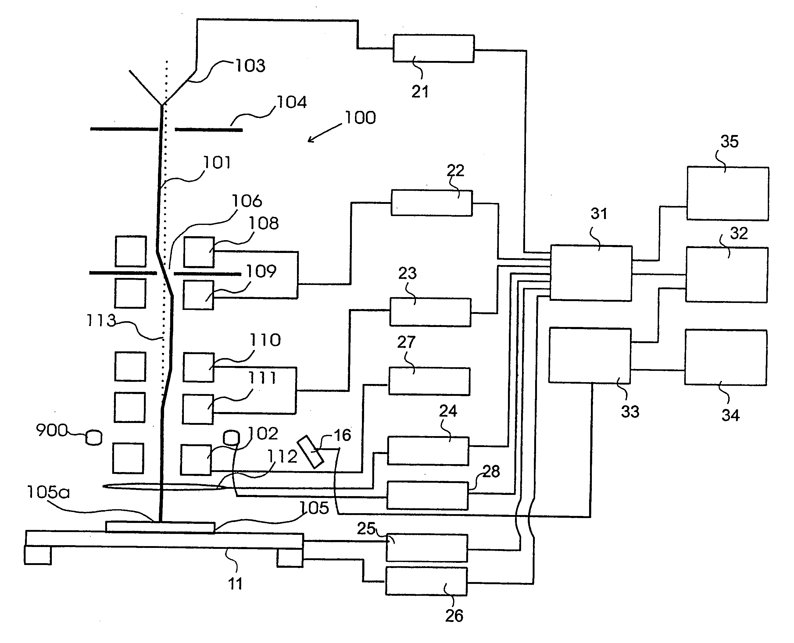
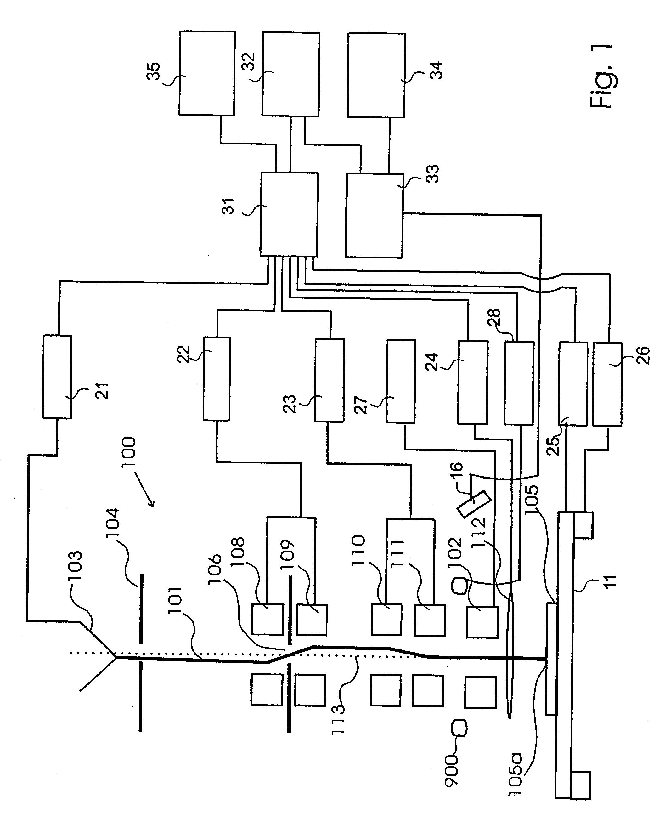
A block diagram of an electron microscope is shown schematically in FIG. 1. The electron microscope 100 comprises an electron gun 103 emitting an electron beam 101, which is extracted by the anode 104. The objective ...


PUM

PropertyMeasurementUnit
frequencyaaaaaaaaaa
frequencyaaaaaaaaaa
frequencyaaaaaaaaaa

Abstract

The invention provides a method for automatically aligning a beam of charged particles with an aperture. Thereby, the beam is defelcted to two edges of the aperture. From the signals required to obtain an extinction, a correction deflection field is calculated. Furter, a method for automatically aligning a beam of charged particles with an optical axis is provided. Thereby a defocusing is introduced and a signal calculated based on an introduced image shift is applied to a deflection unit. Further, a method for correction of the astigmatism is provided. Thereby the sharpness is evaluated for a sequence of frames measured whilst varying the signals to a stigmator.

Description

FIELD OF THE INVENTION The present invention generally relates to charged particle columns and more particularly to a method and an apparatus for alignment and correction of aberrations of a beam of charged particles. More specifically, the present invention also relates to an automatic alignment of a beam of charged particles and automatic correction of aberrations. BACKGROUND OF THE INVENTION Technologies like microelectronics, micromechanics and biotechnology have created a high demand in industry for structuring and probing specimens within the nanometer scale. On such a small scale, probing or structuring is often done with electron beams, which are generated and focussed in charged particle beam devices like electron microscopes or electron beam pattern generators. Charged Particle beams offer superior spatial resolution compared to e.g. photon beams due to their short wavelengths. The spatial resolutions that could possibly be achieved based on wavelength e.g. below 0.01 n...

Claims


Application Information

Patent Timeline
Patent Type & Authority Applications(United States)
IPC IPC(8): A61N5/00G01N21/00G21G5/00H01J3/26H01J37/21H01J37/08H01J37/153H01J37/22H01J37/26
CPCH01J37/1471H01J37/153H01J37/22H01J37/263H01J37/265H01J2237/221H01J2237/045H01J2237/1501H01J2237/1532H01J2237/216H01J37/304
Inventor SHEMESH, DROR
Owner APPL MATERIALS ISRAEL LTD
Why Eureka
Try Eureka