Decentered optical system, light transmitting device, light receiving device, and optical system

a technology of light transmission and optical system, applied in the field of decentered optical system, light transmission device, light receiving device, optical system, can solve the problems of easy obstructing of light beam, affecting the stability of optical communication in space, and affecting the stability of optical communication, so as to achieve stable and reliable optical communication in space, the effect of light loss small and stabl

Inactive Publication Date: 2005-01-20
OLYMPUS CORP
View PDF11 Cites 65 Cited by
  • Summary
  • Abstract
  • Description
  • Claims
  • Application Information

AI Technical Summary

Benefits of technology

According to this invention, optical communication in space can be carried out with little loss of light. In particular, it...

Problems solved by technology

However, because these mirrors are disposed coaxially, the secondary mirror portion is obstructed and optical loss occurs.
As a result, in the case, for example, that an optic...

Method used


Image

  • Decentered optical system, light transmitting device, light receiving device, and optical system
  • Decentered optical system, light transmitting device, light receiving device, and optical system
  • Decentered optical system, light transmitting device, light receiving device, and optical system

Examples


first embodiment

The decentered optical system according to the first embodiment of the present invention will be explained.

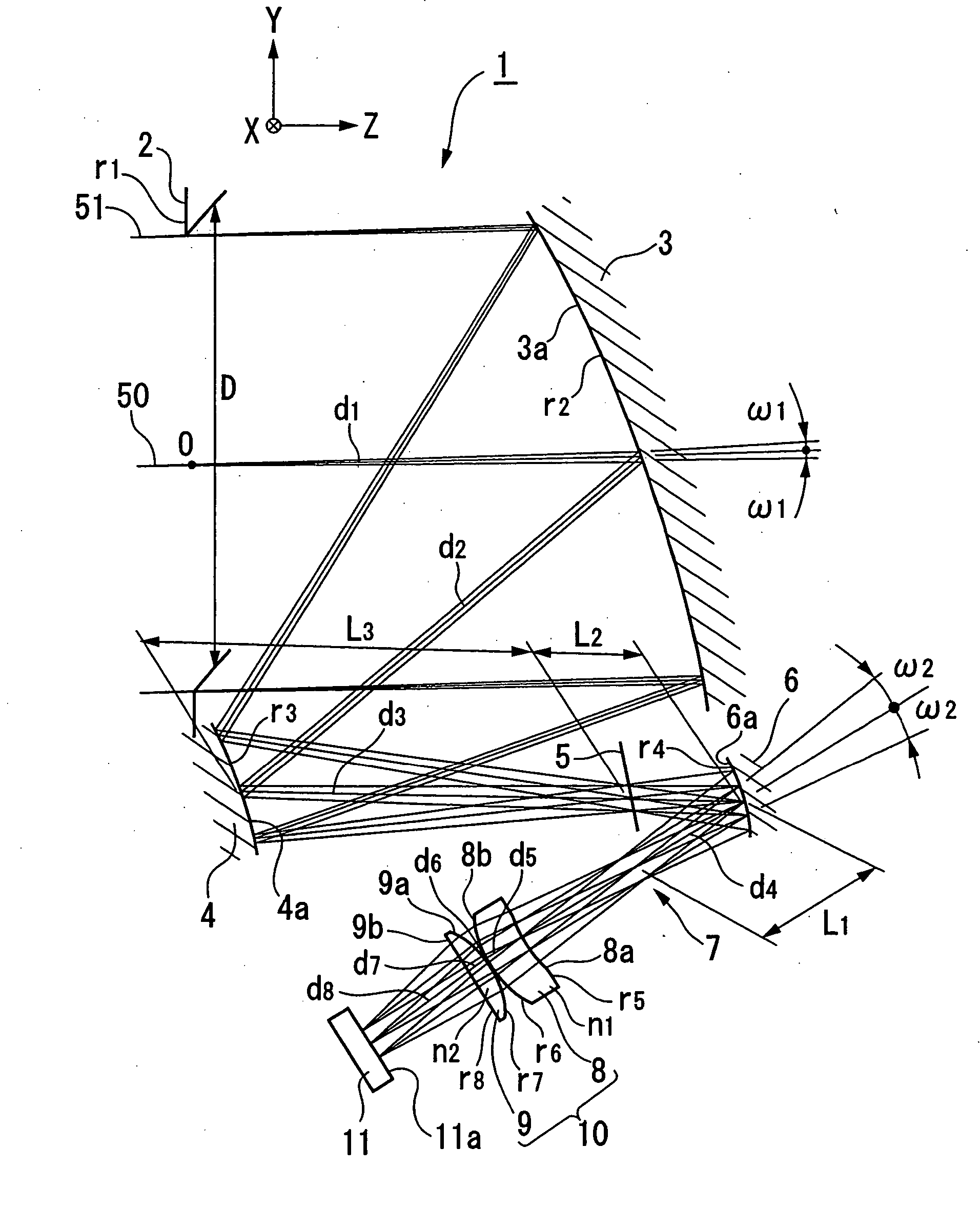
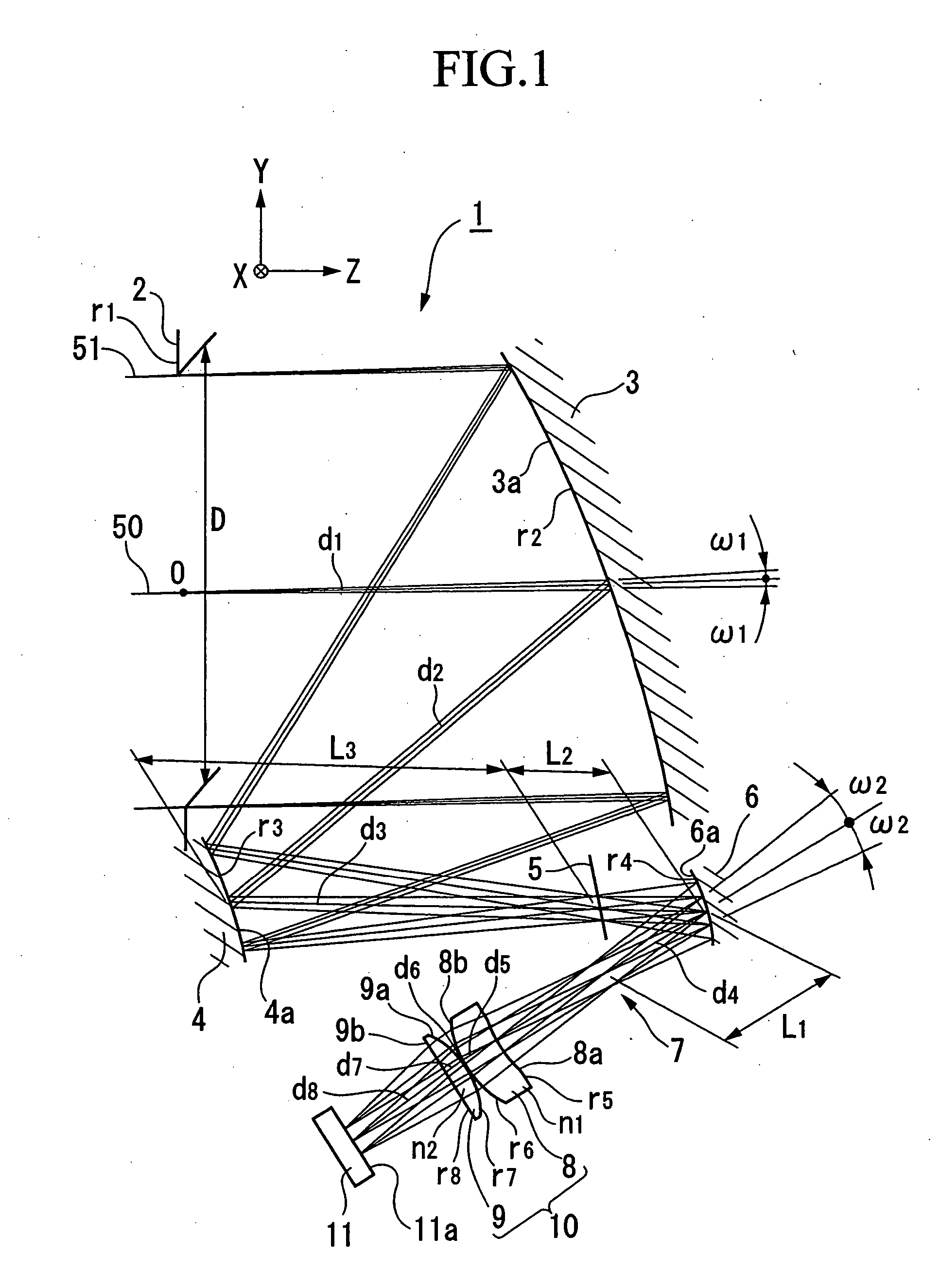
FIG. 1 is a cross-sectional optical path diagram that includes the optical path on an axial principal ray for explaining an example of the decentered optical system according to a first embodiment of the present invention. Note that when the optical path has an incident field angle of 0° and an incident field angle ±ω around the axis perpendicular to the page surface, the light beam is traced by the principal ray and two characteristic rays.

The decentered optical system 1 according to a first embodiment of the present invention will be explained.

The decentered optical system 1 is for forming an image on a light receiving surface 11a after a substantially parallel incident light beam 51 (input light) is made incident on the system, and the schematic structure thereof consists of an aperture stop 2, a reflecting mirror 3 (first optical element), a reflecting mirror 4 (secon...

fourth modification

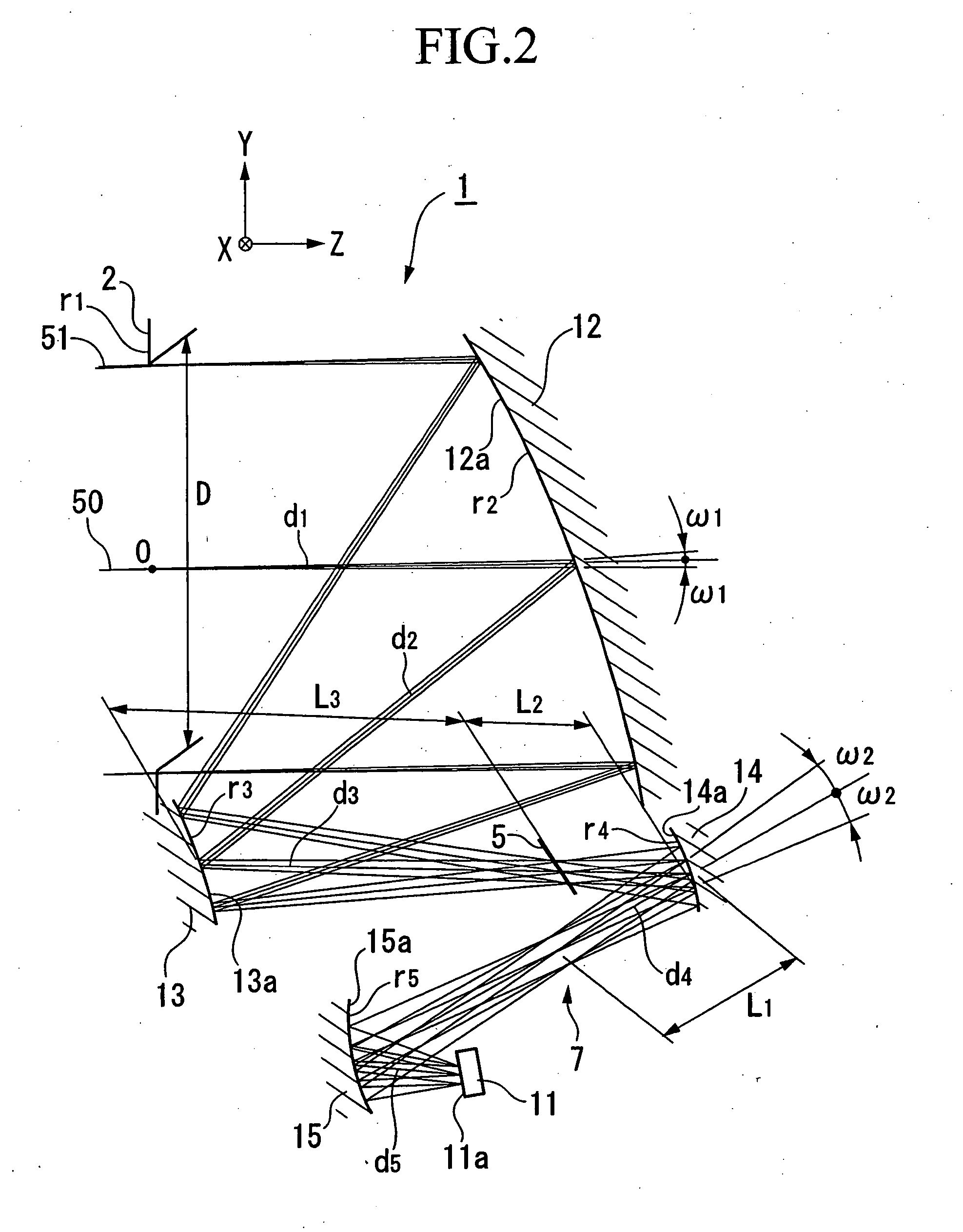
The fourth modification of the decentered optical system 1 will now be explained.

FIG. 5 is a cross-sectional optical path diagram that includes the optical path of the axial principal ray for explaining the fourth modification of the present embodiment.

Instead of the reflecting mirrors 3, 4, and 6 and the focusing device 10 of the embodiment described above, the present modification provides a Fresnel lens 24 (first optical element), a reflecting mirror 25 (second optical element), a reflecting mirror 36 (third optical element), and a Fresnel lens 27 (focusing device). Here, the coefficients of the free-formed surface and the amount of decentration of the reflecting surface 25a (decentered reflecting surface) differ only slightly from the corresponding reflecting surface 4a, and has a substantially identical effect. Thus, its explanation is omitted. Similarly, a reflecting mirror 26 having a reflecting surface 26a consisting of a rotationally asymmetric surface has a function su...

fifth modification

The fifth modification of the decentered optical system 1 will now be explained.

FIG. 6 is a cross-sectional optical path diagram that includes the optical path on the axial principal ray for explaining the fifth modification of the present embodiment.

Instead of the reflecting mirrors 3, 4, and 6 and the focusing device 10 in the embodiment described above, the present modification provides a lens 28 (first optical element), a reflecting mirror 29 (second optical element) a reflecting mirror 30 (third optical element), and a lens 31 (focusing device). In addition, instead of the Fresnel lenses 24 and 27 in the fourth modification, the configuration is substantially identical to one providing the lenses 28 and 31.

The coefficients of the free-formed surface of the reflecting surface and the amount of decentration of reflecting mirror 29 having the reflecting surface 29a (decentered active surface) and the reflecting mirror 30 having the reflecting surface 30a (an optically active...


PUM


Abstract

The decentered optical system is configured by a first, a second and a third reflecting mirror disposed decentered, a focusing device, and a light receiver. The optical path is folded by the first, second, and third reflecting mirrors, aberration correction is carried out by a rotationally asymmetric reflecting surface, and an intermediate image is formed between the second and third reflecting mirrors and another reflecting mirror. The reflected light of the third reflecting mirror is made to form a substantially parallel light beam that forms an exit pupil. An image is formed on the light receiving surface by the focusing device. This decentered optical system is used in a light transmitting device, a light receiving device, and a light transmitting and receiving system, and carries out light tracking by detecting the position of the received light image.

Description

PRIORITY CLAIM Priority is claimed on Japanese Patent Application Nos. 2003-165372 filed Jun. 10, 2003, and 2003-271156 filed Jul. 4, 2003. BACKGROUND OF THE INVENTION 1. Field of the Invention The present invention relates to a decentered optical system, an light transmitting device, a light receiving device, and an optical system, and in particular, relates to a decentered optical system, an light transmitting device, an light receiving device, and an optical system that can by advantageously used when carrying out focusing on a focal plane. 2. Description of the Related Art Conventionally, it is known that a catoptric system has superior properties in comparison to a dioptric system depending on the field of application. The advantages of a catoptric system are that: because chromatic aberration does not occur, an extremely wide band can be covered if the catoptric system consists of reflecting materials and reflecting films that allow reflection spectral characteristics; o...

Claims


Application Information

Patent Timeline
IPC IPC(8): G02B17/06G02B17/08
CPCG02B17/0642G02B17/0663G02B17/0694G02B17/0896G02B17/0832G02B17/0848G02B17/0816
Inventor TAKAHASHI, KOICHITAKAHASHI, JUNKO
Owner OLYMPUS CORP
Why Eureka
Try Eureka