

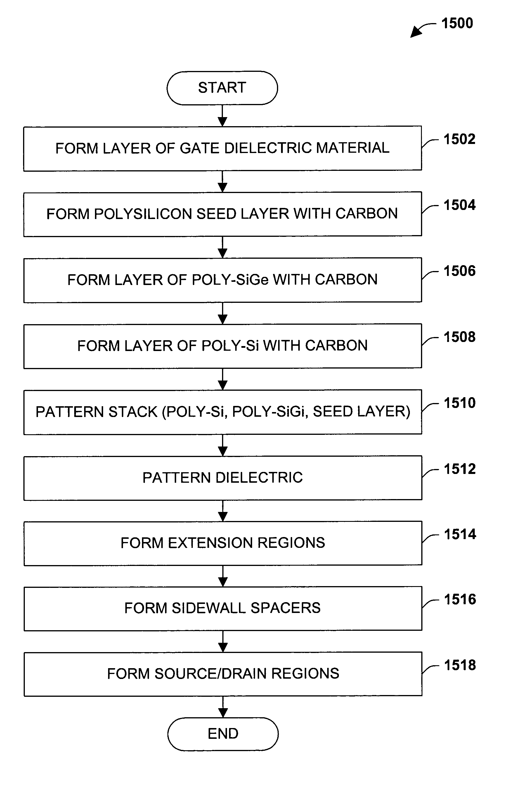
Method to reduce transistor gate to source/drain overlap capacitance by incorporaton of carbon
- Summary
- Abstract
- Description
- Claims
- Application Information
AI Technical Summary
Benefits of technology
Problems solved by technology
Method used
Image

Examples
Embodiment Construction
[0021] One or more aspects of the present invention are described with reference to the drawings, wherein like reference numerals are generally utilized to refer to like elements throughout, and wherein the various structures are not necessarily drawn to scale. In the following description, for purposes of explanation, numerous specific details are set forth in order to provide a thorough understanding of one or more aspects of the present invention. It may be evident, however, to one skilled in the art that one or more aspects of the present invention may be practiced with a lesser degree of these specific details. In other instances, well-known structures and devices are shown in block diagram form in order to facilitate describing one or more aspects of the present invention.
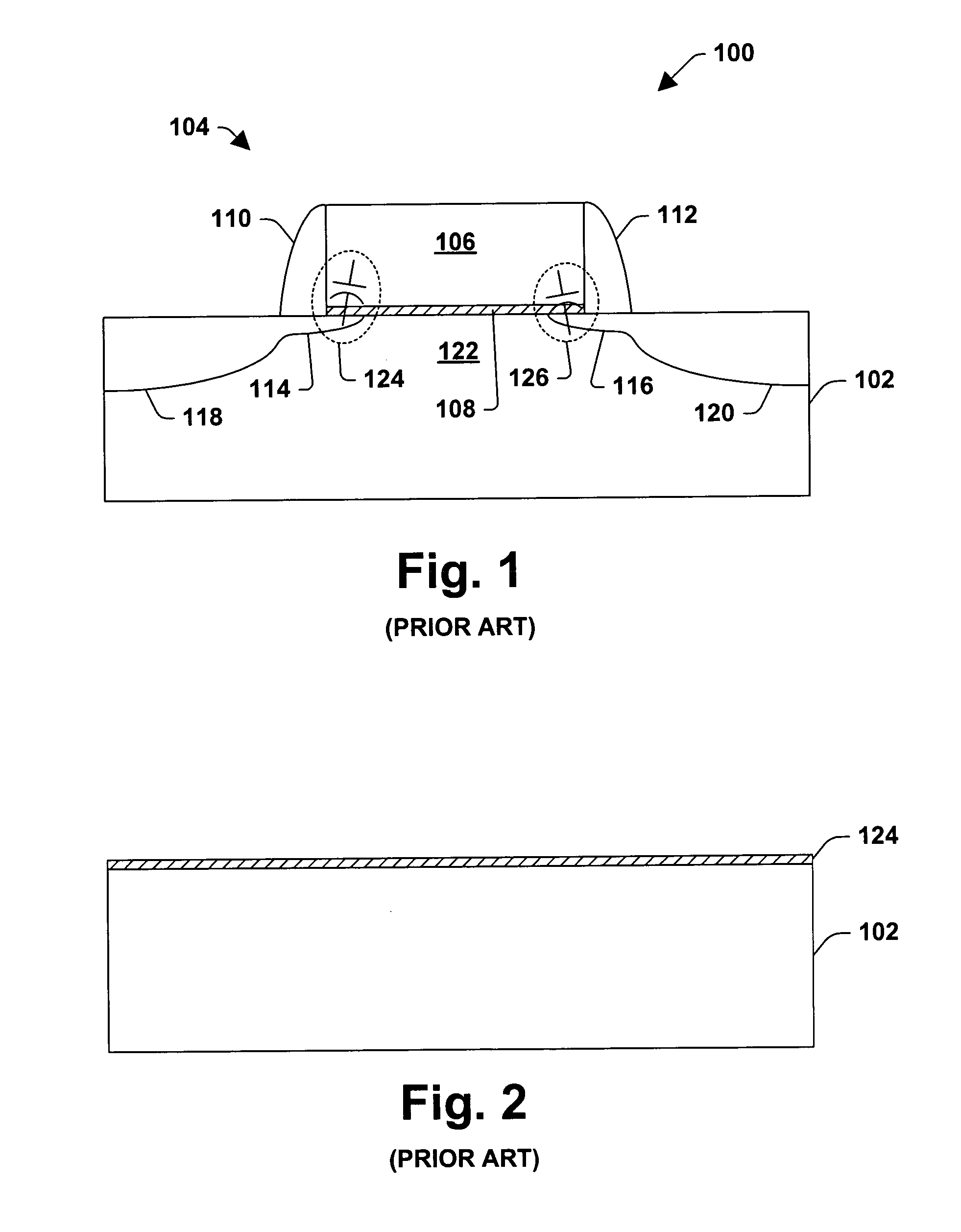
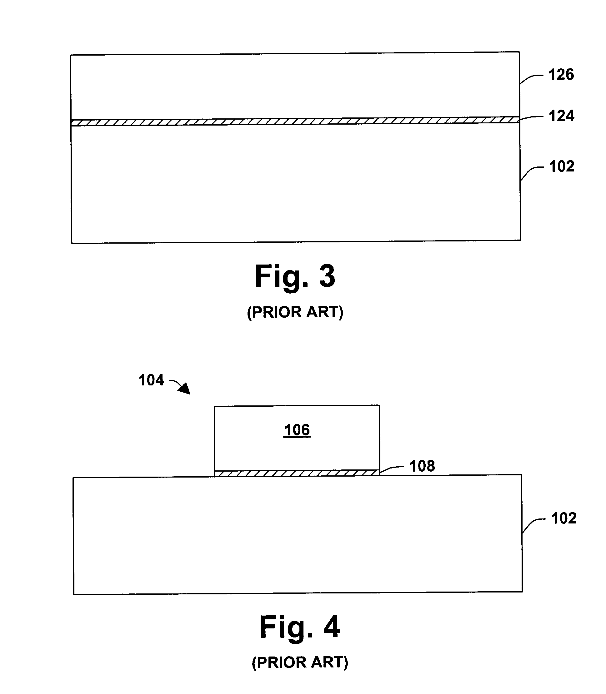
[0022] The present invention pertains to formation of a transistor in a manner that mitigates gate-to-source and / or gate-to-drain overlap capacitance, thereby facilitating, among other things, enhanced switc...
PUM
 Abstract
Description
Claims
Application Information