Method for computing partially coherent aerial imagery
Inactive Publication Date: 2005-01-20
IBM CORP
View PDF9 Cites 119 Cited by
- Summary
- Abstract
- Description
- Claims
- Application Information
AI Technical Summary
Benefits of technology
It is an objective of the present invention to provide a method for obtaining solely analytical expressions for all of the TCC integrals. A further objective of the present invention is to provide an approximate analytical representation for the TCCs that is accurate to within a desired small error, for example, within the precision of a given computer, which is typically on the order of about 106 for typical single precision calculations in current machines. It is yet a further objective of the present invention to provide a method for computing aerial images very rapidly compared to conventional numerical integration techniques, and to within a desired accuracy, for example very close to machine precision. That is, a primary objective of the present invention is to eliminate the tradeoff between speed and accuracy in the simulation of aerial images, achieving both simultaneously.
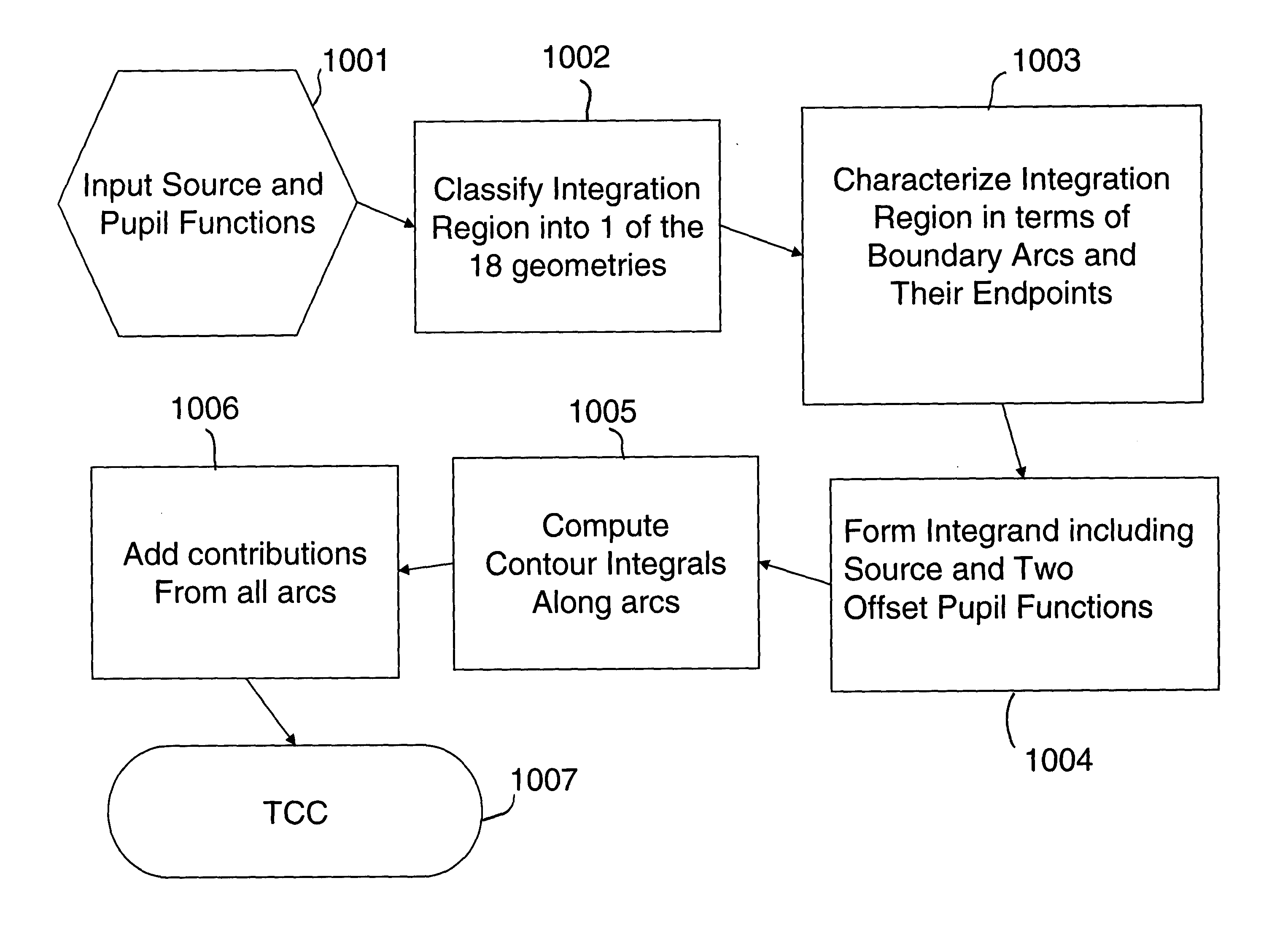
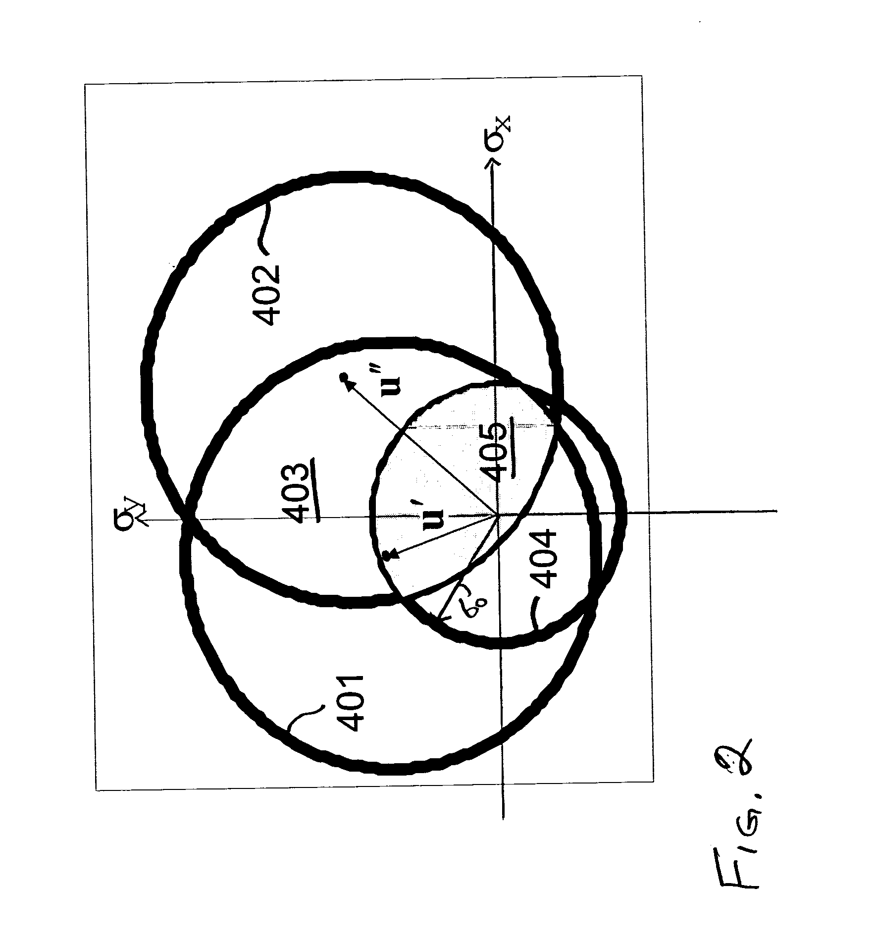
In a further aspect of the present invention, the TCC integration regions are characterized all in terms of a finite set of all the possible geometrical configurations, based on a rotational alignment of the spatial coordinate axis with the axis of symmetry of the integration region. These regions change shape as the spatial frequencies vary, as do the integration limits over which the integrand is to be evaluated. It turns out that there are 18 distinct geometrical configurations when the double integral is used. Furthermore, when Stokes' Theorem is applied, only the boundary of these geometric configurations are considered, and it turns out that the number of distinct configurations is reduced to 9. Such a reduction simplifies the program logic and speeds up calculations.
In a further aspect of the present invention, all of the integrals over the various arcs that comprise the boundaries of the finite geometrical regions is reduced to the same integral form. Since this particular integral does not have an exact representation in terms of purely analytical functions, the present invention provides an approximation for the integrand that differs from the original function in absolute value by a desired small number, for example, on the order of single precision over all possible values of the integration limits. In accordance with the present invention, this new function is chosen such that the error substantially monotonically decreases as the number of terms used in the approximation increases. Furthermore, the integral of the terms of the approximate function is representable in terms of analytical functions that can be computed with a few arithmetic steps. Therefore, the present invention permits computation of a TCC that is accurate to within a desired precision and can be evaluated rapidly using a finite number of arithmetic operations.
Problems solved by technology
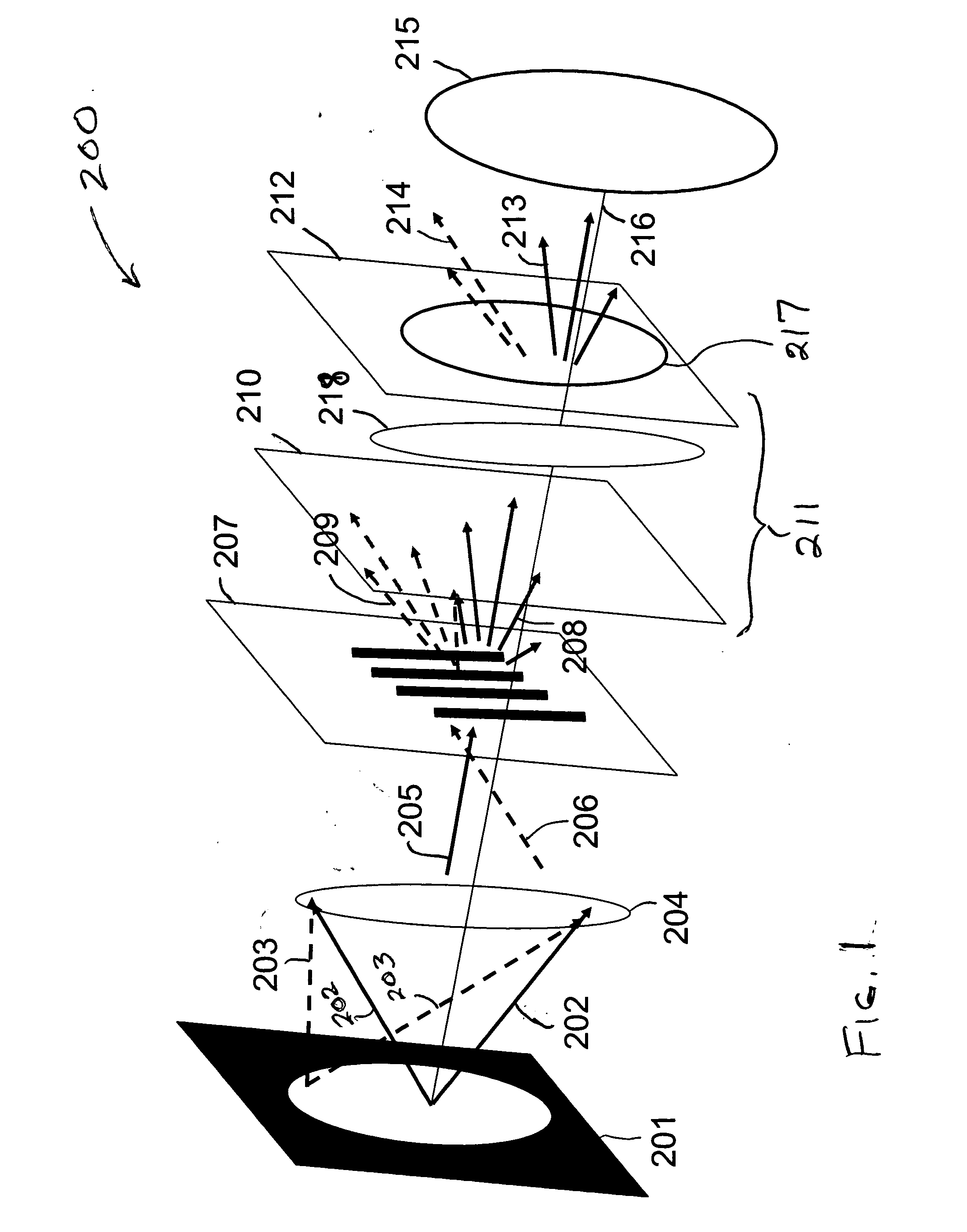
Diffraction, interference and processing effects that occur during the transfer of the image pattern causes the image or pattern formed at the substrate to deviate from the desired (i.e. designed) dimensions and shapes.
These deviations depend on the interaction of the pattern configurations with the process conditions, and can affect the yield and performance of the resulting microelectronic devices.
Without fast and accurate simulation, it would be impossible to employ an strong RET solution in a practical setting.
Thus the accuracy of the simulated image is crucial in obtaining viable mask designs, and the speed of such calculations impacts the cost of designing the masks.
However, there is an inherent uncertainty in these measurements, for example, caused by charge damage to features on the target.
One conventional method of simulating aerial images is to use a gridding algorithm, as in the prior art outlined above, but in order to obtain the precisions required, to obtain the required precision, the smaller grid sizes result in a large number of gridding intervals, which in turn result in impractical computation times. Such gridding methods cannot be used to simulate large portions of a mask in a practical amount of time.
Because of the complexity of the shape of this region, computation of these TCCs is potentially expensive.
This analytical calculation, while exact, tends to be expensive compared with the decomposition techniques in the SOCS method, because each edge required a trigonometric function evaluation.
Nevertheless, such a calculation leaves little doubt as to the overall accuracy of the computation.
This periodic assumption is used by all current lithography simulators, since rigorous image computation over an entire (26 MM)2 field is impractical.
Therefore, even with this simplification, the number of difficult, double integrals that are needed to accurately define the image becomes unmanageable for even moderately large (<10 μm2 area) cells.
Unfortunately, because of the adaptive stepping in the integration, the algorithm runs as long as it needs in order to achieve a certain accuracy.
This can take a long time, especially with pupils that have large phase variations, such as in large defocus and / or aberrations.
There are caveats with this SOCS methodology, however.
While this may suffice for past generations with a larger error tolerance (that is, the larger allowed linewidth variation could accept larger simulation errors, as noted above), this will not serve the future generations, where the error tolerances are rapidly vanishing.
It turns out, however, that the task of calibration of a model to data has gotten so difficult that some physical parameters that are known to be in error—such as the partial coherence or focus—are varied as well.
While this certainly has resulted in a significant increase in computational speed, it is not obvious what accuracy of the image intensity that this method produces, as not only the pupil and source are evaluated on a grid and numerical integration is necessary on at least one dimension, but the expression of the TCC matrix in this orthogonal basis is only exact when an infinite number of terms are used.
Speed is also a major issue, because many thousands of simulations must take place in order to perform a single optimization.
Historically, there has always been a tradeoff between speed and accuracy, in that speed requires one to sample less source integration points, or less eigenfunction kernels in the “fast” algorithms used in Model-Based OPC software.
The trouble is, of course, finding such a solution.
Rigorous analytical methods of aerial images would be preferred to the numerical gridding methods commonly in use today, but are typically impractical because the resulting integrals cannot directly be evaluated in many cases.
While this extended the art significantly, it is still limited to one-dimensional (1D) gratings and small values of the numerical aperture.
While Liebchen's method does potentially reduce the number of TCCs needed, it also introduces a gridding; the combination of the decomposition and gridding methodologies introduce potential inaccuracies.
Further, it is unclear how large values of defocus or aberrations are treated with any accuracy, as all treatments are Taylor expansions of the phases in the frequency variable.
For small aberrations, this is acceptable, but such expansions quickly lose accuracy in the face of even a moderate defocus
Method used
View moreImage
Smart ImageViewing Examples
Examples
case 1 (fig.6a)
Case 1 (FIG. 6A): |v|<v1.
case 2 (fig.6b)
Case 2 (FIG. 6B): u2<0, v2<v3 and v1<|v|<v2.
u2<0, v3<v2 and v1<|v|<v3.
u2>0, v2<v5 and v1<|v|<v2.
u2>0, v2>v5 and v1<|v|<v5.
case 3 (fig.6c)
Case 3 (FIG. 6C): u2<0, v2<v3 and v2<|v|<v3.
u2>0, v2<v5 and v2<|v|<v5.
Login to View More PUM
 Abstract
A method for simulating aerial images is provided where the integrand of a transmission cross-coefficient (TCC) integral is formed from defocused paraxial pupil transfer functions, and contour integration is performed over the boundary of the intersection of the offset pupil functions and the source function. Preferably, the paraxial pupil functions are approximated by a second order Taylor series expansion. The integrand is preferably parameterized in terms of the angles subtending the arcs of the boundary of the integration region, and the integrand is further approximated by an expansion of analytically integrable terms having an error term that substantially monotically decreases as the number of expansion terms increases. Additional factors such as aberrations and amplitude variations can be included by using functions that are simply multipied with the defocused paraxial pupil functions in the integrand. The integrands provide fast computations of TCC integrals that are accurate to within a desired tolerance.
Description
TECHNICAL FIELD The present invention relates in general to manufacturing processes that require lithography and, in particular, to methods of designing photomasks and optimizing lithographic and etch processes used in microelectronics manufacturing. BACKGROUND INFORMATION During microelectronics manufacturing, a semiconductor wafer is processed through a series of tools that perform lithographic processing, followed by etch processing, to form features and devices in the substrate of the wafer. Such processing has a broad range of industrial applications, including the manufacture of semiconductors, flat-panel displays, micromachines, and disk heads. The lithographic process allows for a mask or reticle pattern to be transferred via spatially modulated light (the aerial image) to a photoresist (hereinafter, also referred to interchangeably as resist) film on a substrate. Those segments of the absorbed aerial image, whose energy (so-called actinic energy) exceeds a threshold ener...
Claims
Login to View More Application Information
Patent Timeline
 IPC IPC(8): G03F1/14G03F7/20G06F17/10G06F17/50G06G7/62
CPCG03F1/144G06F17/10G03F7/705G03F1/36
Inventor GORDON, RONALD L.
Owner IBM CORP
Features
- R&D
- Intellectual Property
- Life Sciences
- Materials
- Tech Scout
- Unparalleled Data Quality
- Higher Quality Content
- 60% Fewer Hallucinations
Learn More Browse by: Latest US Patents, China's latest patents, Technical Efficacy Thesaurus, Application Domain, Technology Topic, Popular Technical Reports.
© 2025 PatSnap. All rights reserved.Legal|Privacy policy|Modern Slavery Act Transparency Statement|Sitemap|About US| Contact US: help@patsnap.com


