In addition to the issue of safety as described in (1), a further
advantage of the present invention relating to the installation of same within human or animal habitats is provided by virtue of its inherent low vibration. As most popular wind
energy converter devices operate well within a turbulent airflow and relatively close to the ground, large asymmetric forces are imposed upon the high speed rotors or turbine blades of these devices and are transmitted through the rotor or turbine blades and into the supporting structures. Because of this, it is not practical to
mount these devices on top of
high rise buildings as the vibrations would be experienced; felt or heard; by the occupants of the building. This is a further important factor that limits or precludes the installation of popular wind
energy converter devices atop man-made inhabited structures. As will be understood in the following sections of this application, the present invention inherently provides in essence a pneumatic transmission that buffers and virtually eliminates these types of vibrations that originate in the turbulent airflow
layers in which wind energy
converters generally operate.
relating to the installation of same within human or animal habitats is provided by virtue of its inherent low vibration. As most popular wind
energy converter devices operate well within a turbulent airflow and relatively close to the ground, large asymmetric forces are imposed upon the high speed rotors or turbine blades of these devices and are transmitted through the rotor or turbine blades and into the supporting structures. Because of this, it is not practical to
mount these devices on top of
high rise buildings as the vibrations would be experienced; felt or heard; by the occupants of the building. This is a further important factor that limits or precludes the installation of popular wind energy converter devices atop man-made inhabited structures. As will be understood in the following sections of this application, the present invention inherently provides in essence a pneumatic transmission that buffers and virtually eliminates these types of vibrations that originate in the turbulent airflow
layers in which wind energy
converters generally operate.
3. Utilization and conversion of higher speed, higher energy winds.
Popular wind energy converters may have large rotor blade diameters of up to 40 meters or even greater. Generally these large commercial wind energy converters are limited to a maximum wind energy usage equivalent to about 25
miles per hour wind speed. This means that even when wind speeds exceed about 25 mph, the maximum energy that the rotor driven wind energy converter is able to convert to mechanical or
electric energy is no greater than that obtainable in a 25 mph wind. This does not mean that the rotor device is unable to operate in winds exceeding 25 mph. The technical rational for this limitation relates to issues of mechanical loading on the rotor blades, rotor bearings and related mechanical structures given that this loading increases as the square of increasing wind speeds and airflow turbulence. In the end, it is an issue of design and production costs versus returns as it relates to the
accommodation of higher wind speeds and associated increases in airflow turbulence. The present invention does not suffer from this limitation to the degree suffered by rotor or turbine driven wind energy converters. The reason for this is that the present invention utilizes a fundamentally different method for the conversion of wind energy that employs directly the principles of differential static pressures according to the renown Bernoulli's equations, and avoids the requirement for large
diameter rotor or turbine blades that directly experience the mechanical loading and mechanical shock of higher speed winds and airflow turbulence. As such, and for reasons that will be more fully disclosed in following sections of this application, the present invention will tolerate, and more, convert the
kinetic energy provided by higher wind speeds and airflow turbulence into usable mechanical or electrical energy.
Prior art venturi or vacuum driven devices, especially those that use multiple venturi devices suffer vacuum losses under conditions of turbulent wind; wind with varying speeds and directions. The result of this turbulence is to produce local variations of vacuum pressures within a single venturi, and between individual venturis. Unless otherwise prevented or reduced, the effect is that areas of higher
vacuum pressure may draw air from the locales of lower
vacuum pressure either within a particular venturi, or from a nearby interconnected venturi, rather than applying the
vacuum pressure onto the turbine or energy converter device. It is a substantial object of the present invention to provide a means to eliminate or greatly reduce these potential losses and thereby enable the device to more efficiently extract energy from higher speed and often associated higher turbulence winds.
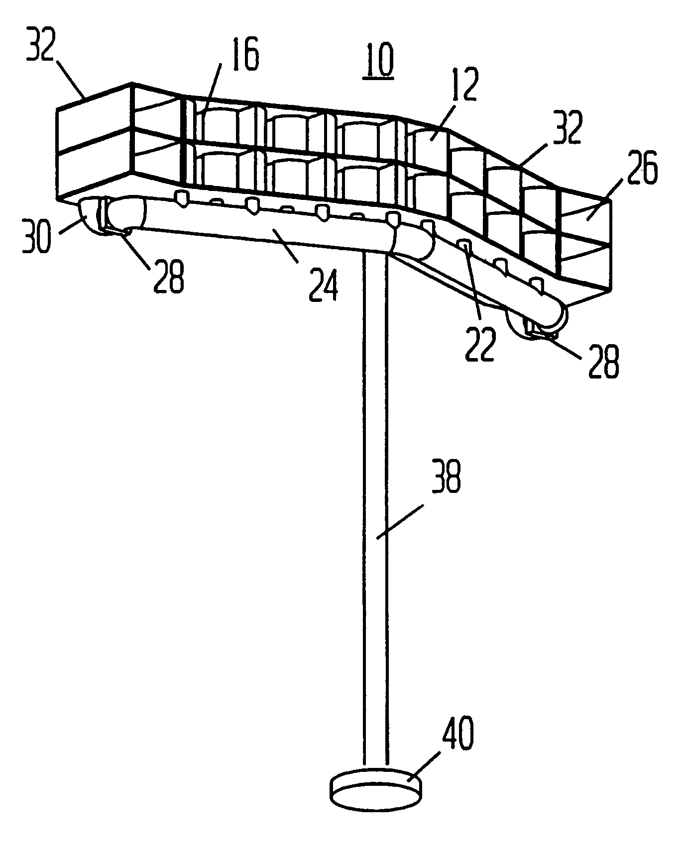
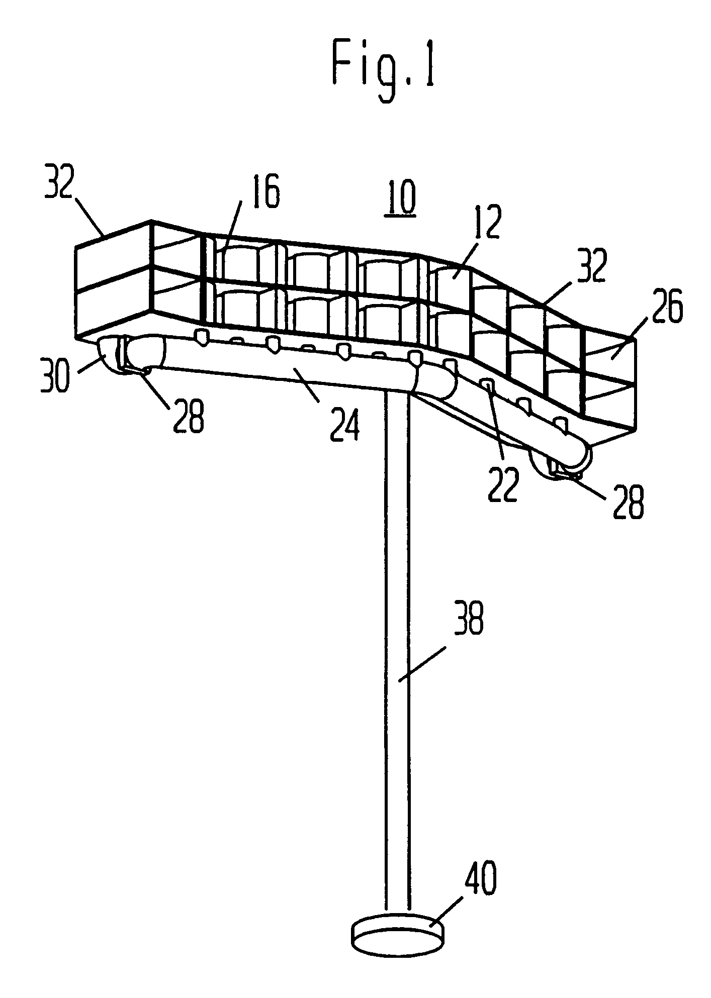
Prior art venturi or vacuum driven devices having multiple venturi devices do not provide a means to contain all of the elements including the turbines or energy converter devices within a single integrated structure. No means therefore is provided, in the prior art, to direct the venturis of these devices, as a group, into the oncoming wind. It is an important object of the present invention to provide a means to integrate most or all of the components of the present invention into a single integrated structure and as well to provide an overall aerodynamic design such that the entire structure will self-orient appropriately into the oncoming wind solely by the action of the wind upon the device. Although such means is provided by many conventional rotor type wind energy converters, such means is not suggested or proposed by the prior art for vacuum driven or venturi type wind energy converters.

