
Apparatus and method for noise sensitivity improvement to a switching system

a switching system and apparatus technology, applied in the field of switching systems, can solve the problems of noise sensitivity, noise interference, noise sensitivity, etc., and achieve the effect of reducing noise interference to the switching system, noise sensitivity, and noise sensitivity

Inactive Publication Date: 2005-01-27
RICHTEK TECH
View PDF3 Cites 43 Cited by
  • Summary
  • Abstract
  • Description
  • Claims
  • Application Information

AI Technical Summary

Benefits of technology

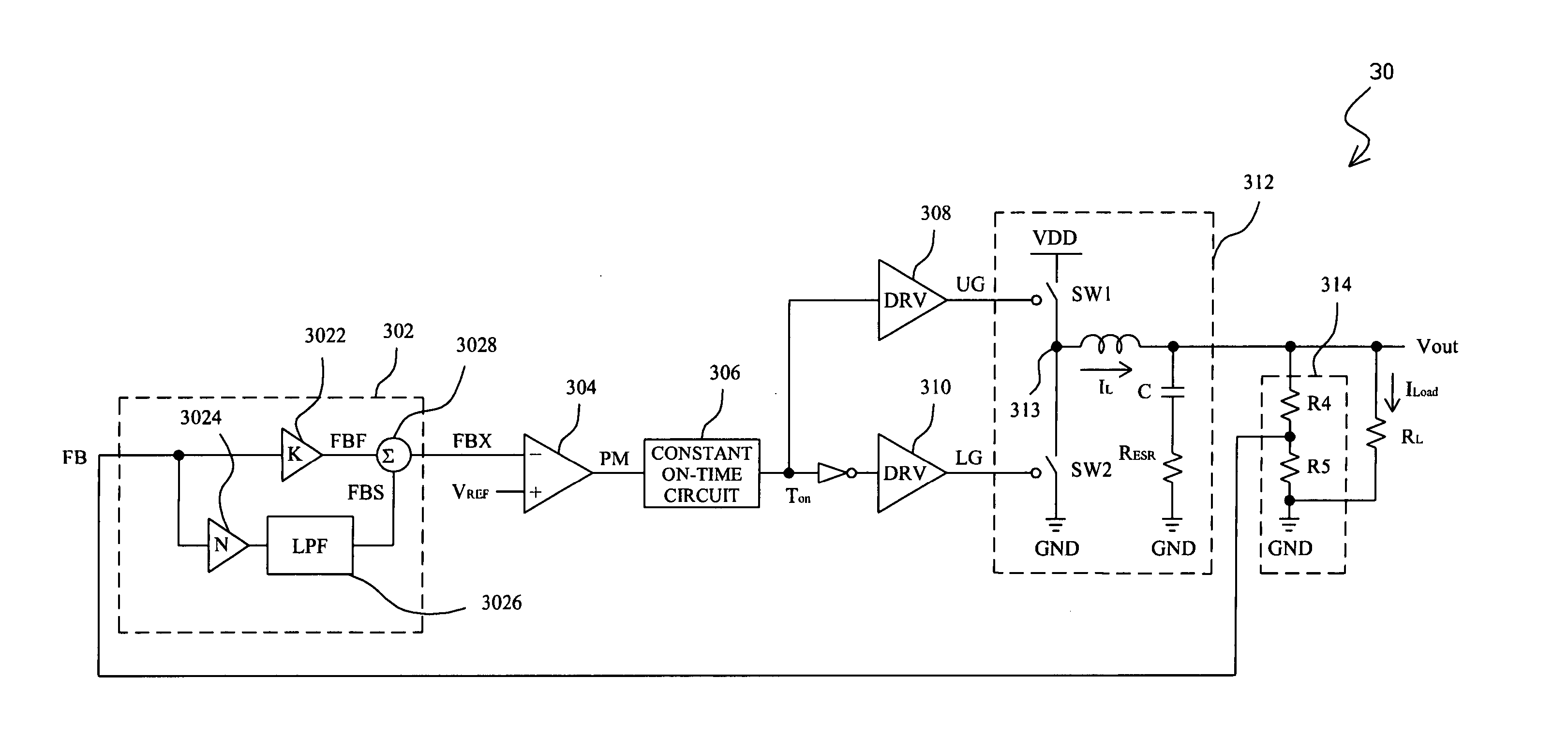
The present invention provides an apparatus and method for improving the noise sensitivity of a switching system. The apparatus includes a voltage sense circuit to generate a feedback signal, an amplifier to amplify the feedback signal, a filter to filter one of the amplified signals, and a summing circuit to combine the two filtered signals. This results in a combined signal with reduced noise interference. The method involves amplifying the feedback signal with two gains, filtering one of the signals, and combining the two signals to reduce noise interference. The invention is applicable to both fast transient response and noise sensitivity improvement in variable-frequency switching systems.

Problems solved by technology

The conventional fixed-frequency pulse width modulation (PWM) controller has poor transient response.
For the ultra-fast transient response characteristic, however, the output capacitor of a variable-frequency PWM controller system is smaller than that of a fixed-frequency PWM controller system, and another problem, noise sensitivity, is introduced eventually.
The topology has fast transient response, but induces noise sensitivity problem.

Method used


Image

  • Apparatus and method for noise sensitivity improvement to a switching system
  • Apparatus and method for noise sensitivity improvement to a switching system
  • Apparatus and method for noise sensitivity improvement to a switching system

Examples


first embodiment

[0028]FIG. 4 shows the first embodiment according to the present invention, in which a switching system 30 comprises an apparatus 302 for noise sensitivity improvement to the switching system 30, in addition to a comparator 304, a constant on-time circuit 306, two drivers 308 and 310, an output stage 312, and a voltage sense circuit 314. The output stage 312 includes a high-side switch SW1 connected between a supply voltage VDD and a phase node 313, a low-side switch SW2 connected between the phase node 313 and ground GND, an inductor L connected between the phase node 313 and an output Vout, and a capacitor C having an equivalent series resistance RESR connected between the output Vout and ground GND. The voltage sense circuit 314 has two resistors R4 and R5 connected in series between the output Vout and ground GND, to sense the output voltage Vout of the switching system 30 to generate a feedback signal FB. The apparatus 302 generates a combined signal FBX according to the feedba...

second embodiment

[0034]FIG. 7 shows the second embodiment according to the present invention, in which, similar to the switching system 30 of FIG. 4, a switching system 50 comprises a constant on-time circuit 306, two drivers 308 and 310, an output stage 312, and a voltage sense circuit 314. However, the apparatus 502 for noise sensitivity improvement hereof comprises an amplifier circuit 504, a voltage generator 506, an RC filter 508, a comparator 510 and a resistor R1. The RC filter 508 includes a resistor R2 and a capacitor C1 connected in parallel, and the amplifier circuit 504 includes two substantially equivalent transconductive amplifiers 5042 and 5044. The transconductive amplifiers 5042 and 5044 transfer the differential of the feedback signal FB and the reference VREF1 to output currents PM1 and PM2 and both the output currents PM1 and PM2 are inverted to each other due to their inverted inputs. The voltage generator 506 includes a voltage follower to provide a reference VREF2′ from a refe...


PUM


Abstract

In a noise sensitivity improved switching system and method thereof, comprised sensing the output voltage of the switching system to generate a feedback signal, respectively amplifying the feedback signal by two gains to generate two signals in phase or out of phase, filtering one of the two amplified signals, and summing or comparing the filtered signal and the other one, thereby reducing the noise interference to the switching system.

Description

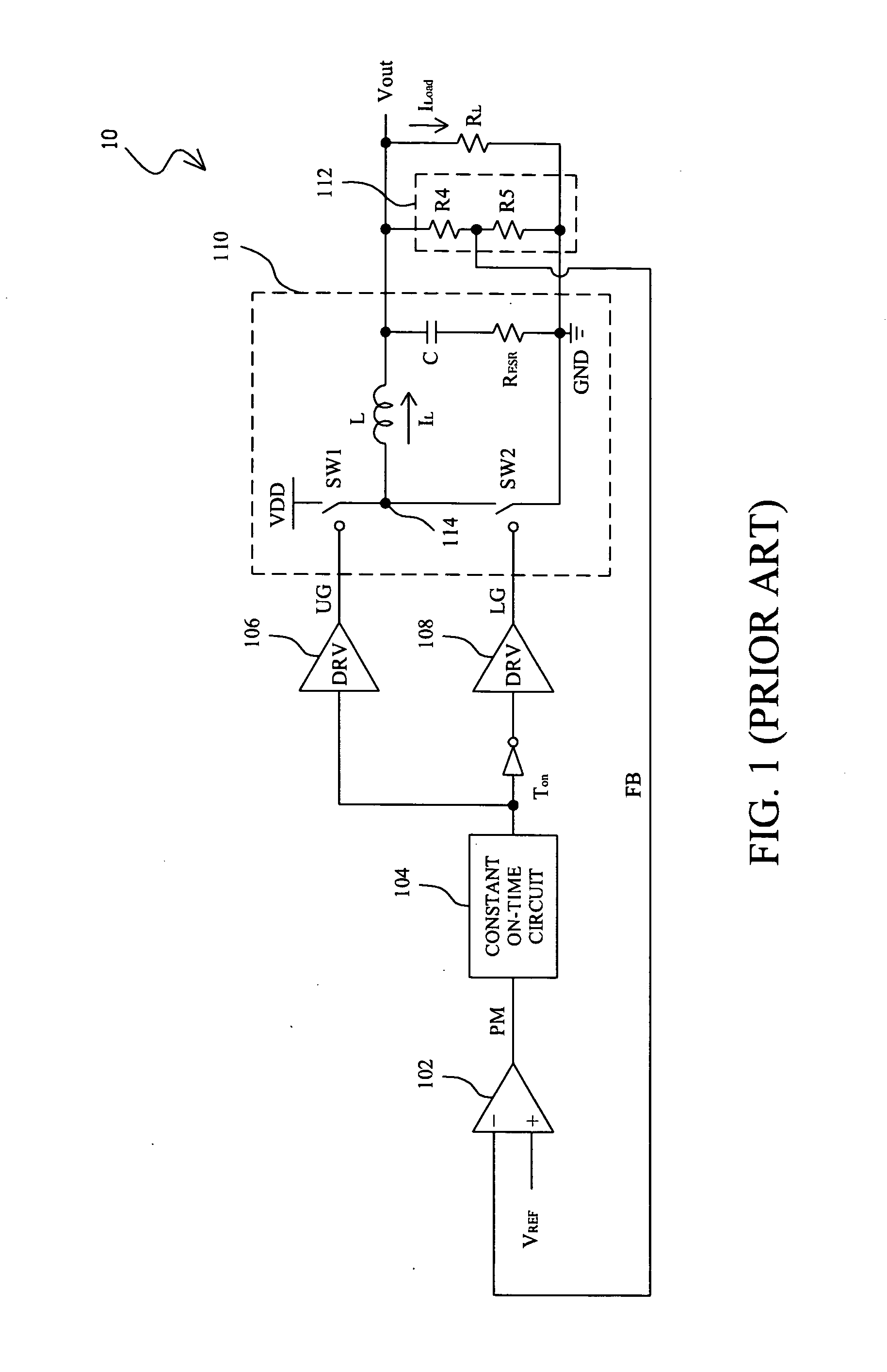
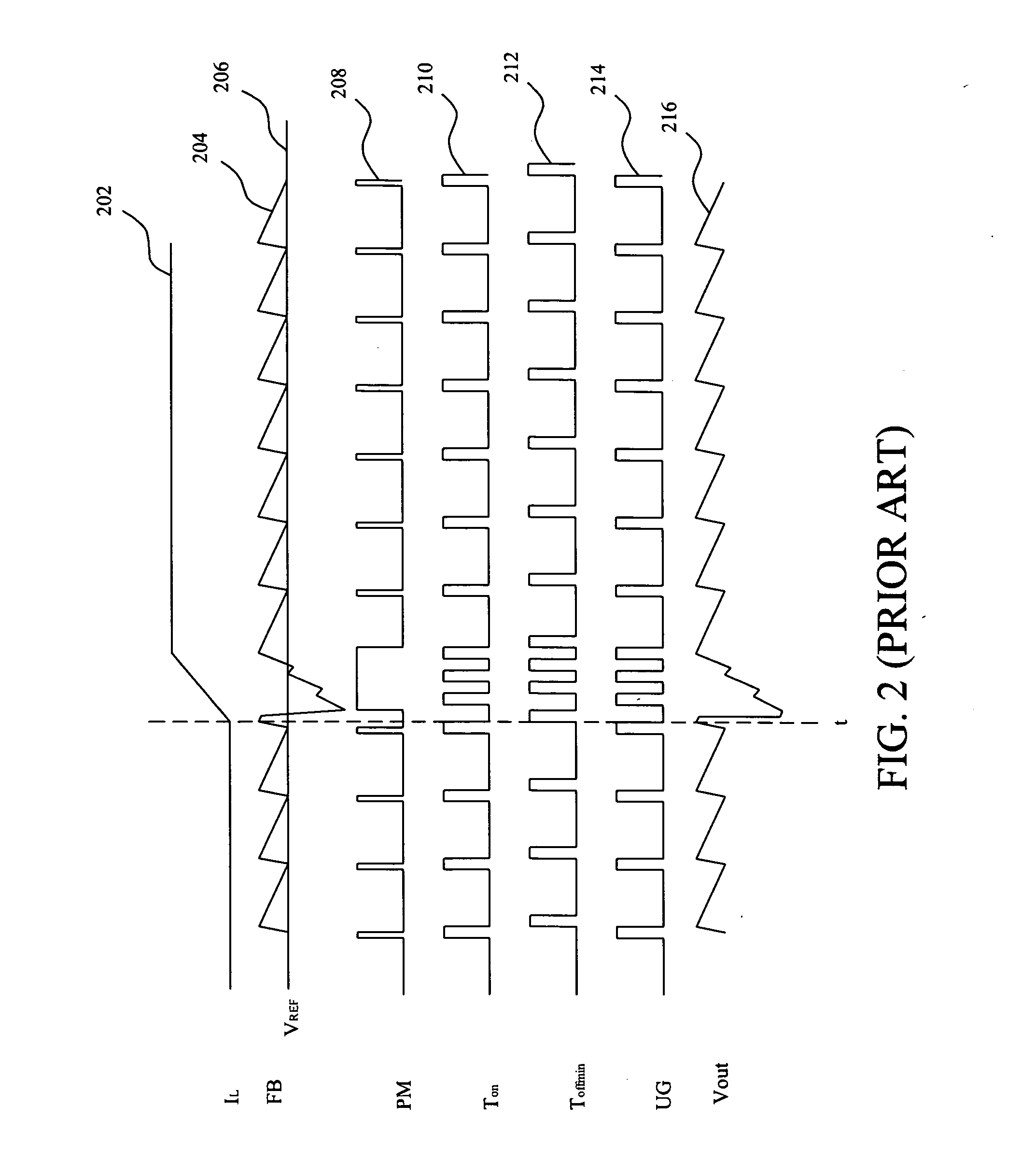
FIELD OF THE INVENTION [0001] The present invention relates generally to a switching system and more particularly, to an apparatus and method for noise sensitivity improvement to a switching system. BACKGROUND OF THE INVENTION [0002] The conventional fixed-frequency pulse width modulation (PWM) controller has poor transient response. Recently, people devote to develop variable-frequency PWM controller system to overcome this issue. For the ultra-fast transient response characteristic, however, the output capacitor of a variable-frequency PWM controller system is smaller than that of a fixed-frequency PWM controller system, and another problem, noise sensitivity, is introduced eventually. The popular variable-frequency PWM controller senses the ripple of the output voltage of the switching system to be a ramp to compare with a reference so as for its system control. For example, as shown in FIG. 1, a switching system 10 comprises an error amplifier 102, a constant on-time circuit 104...

Claims


Application Information

Patent Timeline
Patent Type & Authority Applications(United States)
IPC IPC(8): H02M3/158H03F3/217H03K7/08
CPCH02M3/1588Y02B70/1466H03K7/08H03F3/217Y02B70/10
Inventor HUANG, JIAN-RONGLIU, KUO-PINGHUANG, KENTTAI, LIANG-PIN
Owner RICHTEK TECH
Learn More