
Source synchronous I/O bus retimer

a source synchronous and synchronous technology, applied in the field of digital signal transmission, can solve the problems of inability to achieve the same signal, and inability to meet the needs of multiplex communication, etc., and achieve the effect of improving signal integrity

Active Publication Date: 2005-01-27
ORACLE INT CORP
View PDF8 Cites 22 Cited by
  • Summary
  • Abstract
  • Description
  • Claims
  • Application Information

AI Technical Summary

Benefits of technology

[0009] Generally speaking, a device is contemplated which is configured to repeat source synchronous data. In one embodiment, the device is configured to receive source synchronous data via a first interface, recover the received data and clock signal, and transmit source synchronous signals corresponding to the received signals with improved signal integrity.

Problems solved by technology

While utilizing a synchronous approach may simplify certain aspects of the design process, this approach is not without its problems.
One such problem is that of clock skew.
An additional consequence of using the synchronous design approach and distributing a clock signal throughout a system is the inherent phase delay that may accumulate.
In a design where higher frequencies and performance are desired, these delays ultimately may cause the synchronous design approach to be untenable.
While source synchronous designs may provide certain advantages over synchronous designs, they are not without their own problems.
In addition, certain systems may require transmitting signals over relatively long distances.
Even with the greater lengths which may be achieved using source synchronous designs, jitter and other signal degradation may limit the effective length of a transmission line.
Further, signal degradation may also reduce the effective operating frequency which can be achieved.

Method used


Image

  • Source synchronous I/O bus retimer
  • Source synchronous I/O bus retimer
  • Source synchronous I/O bus retimer

Examples


Embodiment Construction

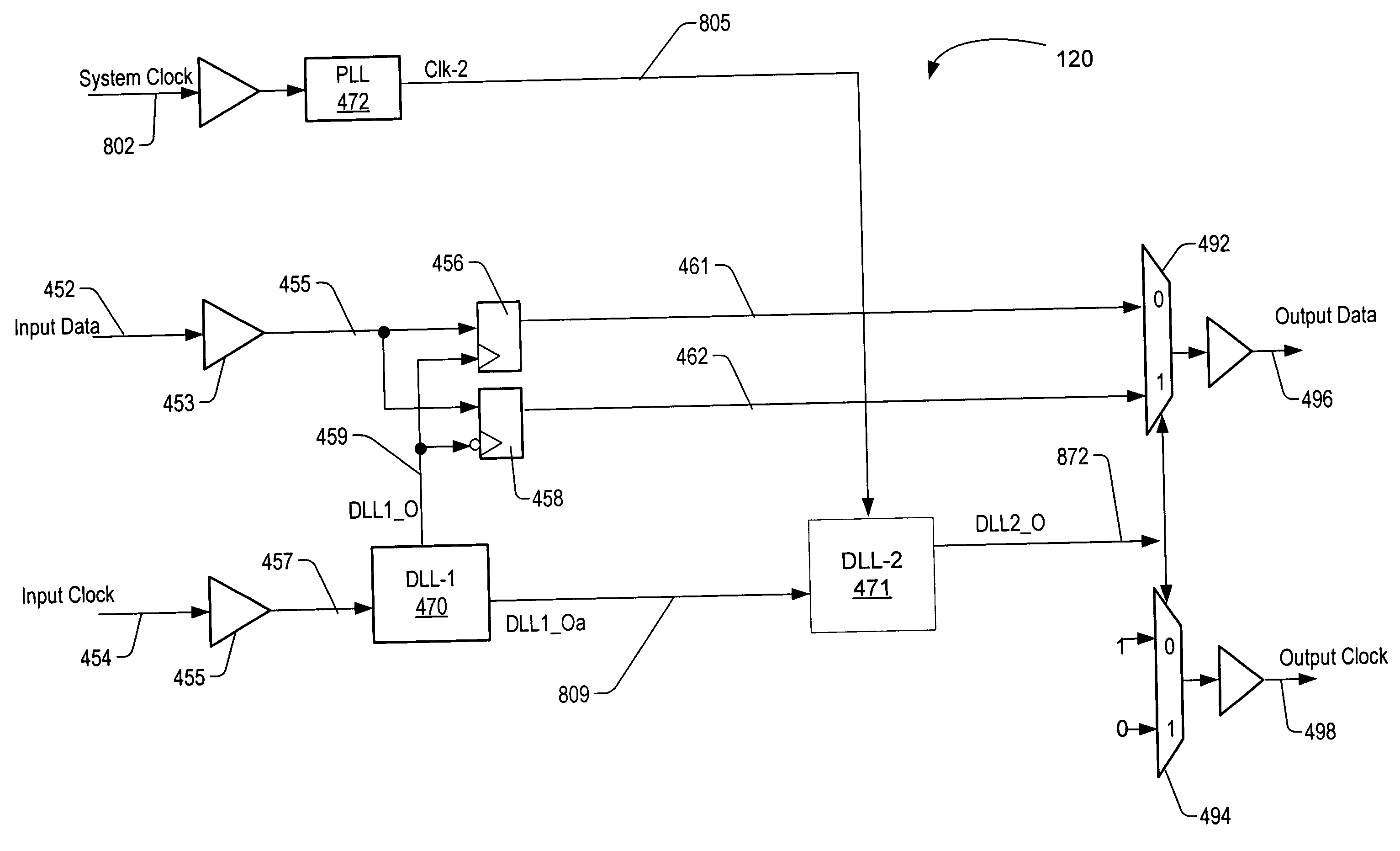
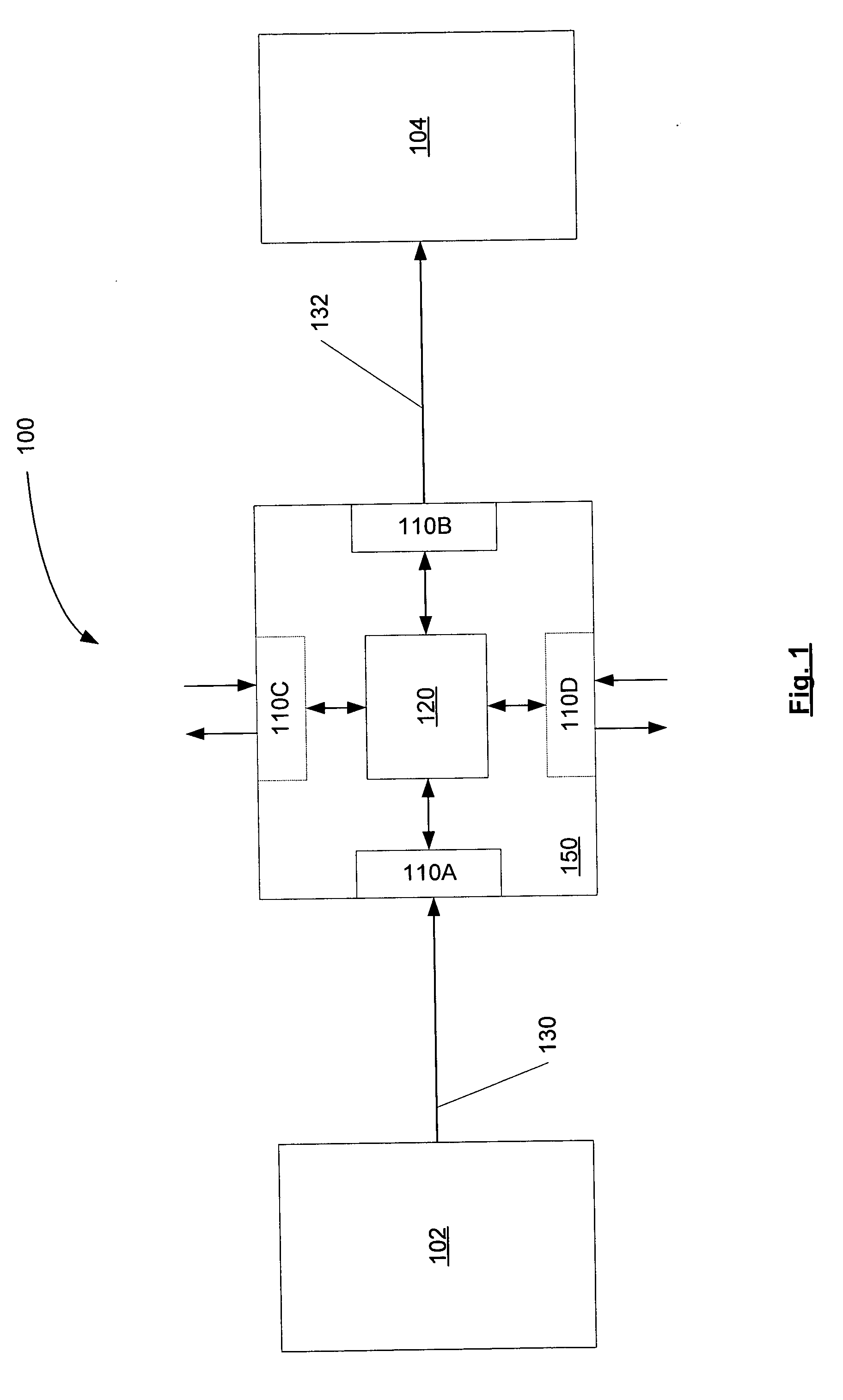
[0020]FIG. 1 illustrates one embodiment of a source synchronous system 100 configured to transmit signals. In the example shown, a source device 102 is configured to convey signals to a destination device 104. Also shown in FIG. 1 is a retiming repeater chip 150 coupled between source device 102 and destination device 104. Retimer chip 150 includes input port 110A which is coupled to receive source synchronous signals from source device 102 via bus 130. Retimer chip 150 also includes output port 110B which is coupled to convey source synchronous signals to destination device 104 via bus 132. Also included in retimer chip 150 is circuitry 120, and optional additional ports 110C and 110D.

[0021] In one embodiment, source device 102 and destination device 104 may be physically separated by such a distance that signal degradation precludes efficient signal transmission directly from source device 102 to destination device 104. Therefore, rather than directly coupling source device 102 t...


PUM


Abstract

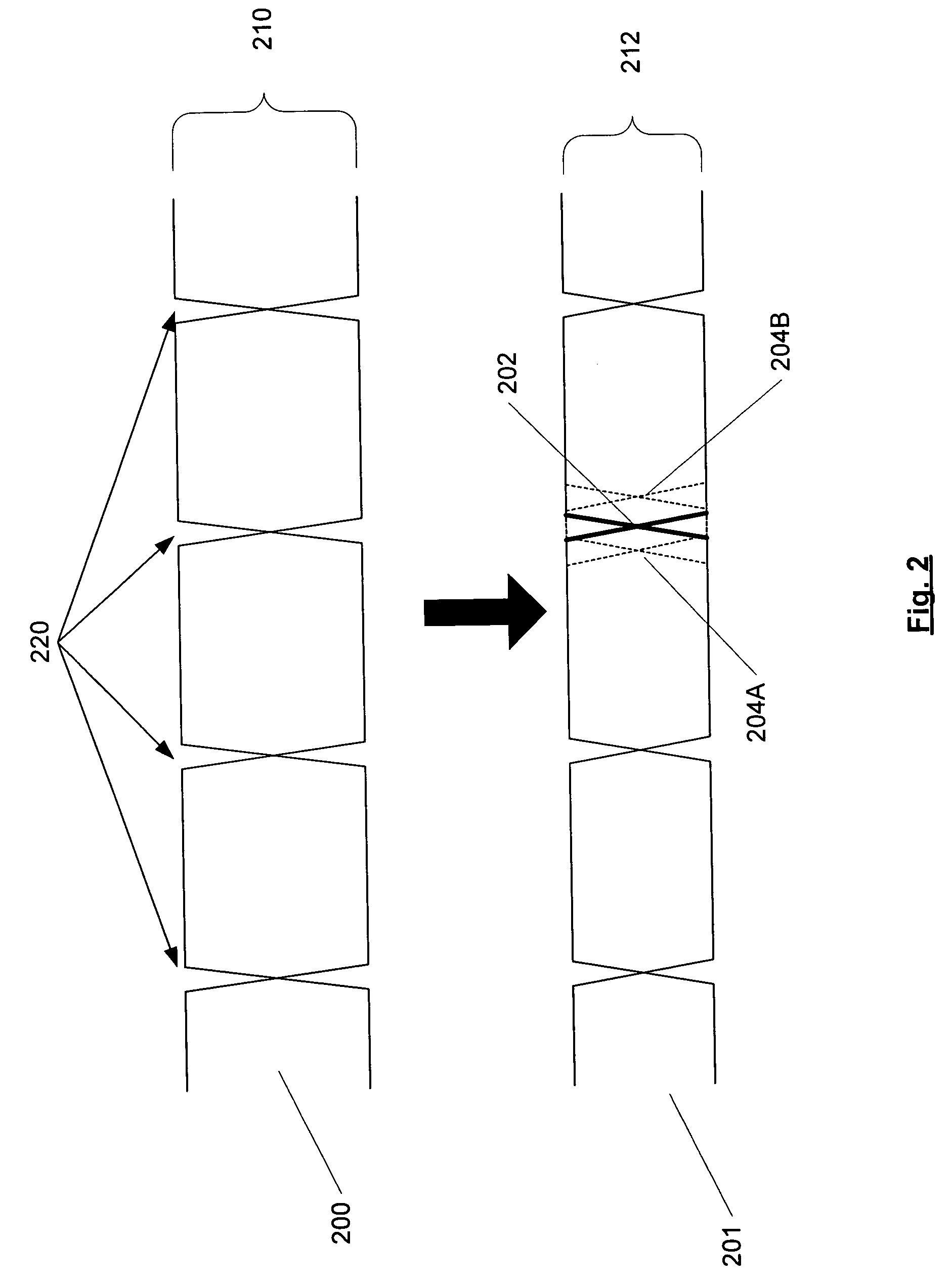
A device configured to recover and repeat source synchronous data. The device is configured to receive source synchronous data via a first interface and recover the received data utilizing a first clock signal which is generated to be approximately ninety degrees out of phase with the received clock signal. A second clock signal is generated to be in phase with the received source synchronous clock signal. The second clock signal is the utilized to select a newly generated clock signal and latched data for transmission in a source synchronous manner. The device is further configured to shift the phase of the generated first clock signal to be approximately ninety degrees out of phase with the received data signal.

Description

BACKGROUND OF THE INVENTION [0001] 1. Field of the Invention [0002] This invention is related to the field of digital communications and, more particularly, to the transmission of digital signals. [0003] 2. Description of the Related Art [0004] The design of advanced digital communication systems requires careful attention to the reliable transmission and receipt of signals in order to ensure proper functioning. One popular design methodology is that of synchronous design. Generally speaking, synchronous designs utilize a central clock which is distributed to various parts of the design. While utilizing a synchronous approach may simplify certain aspects of the design process, this approach is not without its problems. One such problem is that of clock skew. Because a central clock signal may be distributed to various parts of a system via board traces, backplanes, interconnects, and the like, clock skew may exceed that which can be tolerated by registers and other elements. Consequ...

Claims


Application Information

Patent Timeline
IPC IPC(8): H04J3/06H04L7/033H04L25/60
CPCH04L7/0337H04J3/0685
Inventor SMITH, BRIAN L.JONG, JYH-MING
Owner ORACLE INT CORP
Learn More