Fan motor speed control circuit

Active Publication Date: 2005-01-27
DELTA ELECTRONICS INC
View PDF6 Cites 13 Cited by
  • Summary
  • Abstract
  • Description
  • Claims
  • Application Information

AI Technical Summary

Benefits of technology

[0010] The advantage of this invention is to reduce the vibration degree and noise problem occurred

Problems solved by technology

A conventional fan motor rotation speed control circuit cannot avoid the noise problem caused by th

Method used


Image

  • Fan motor speed control circuit
  • Fan motor speed control circuit
  • Fan motor speed control circuit

Examples


Example

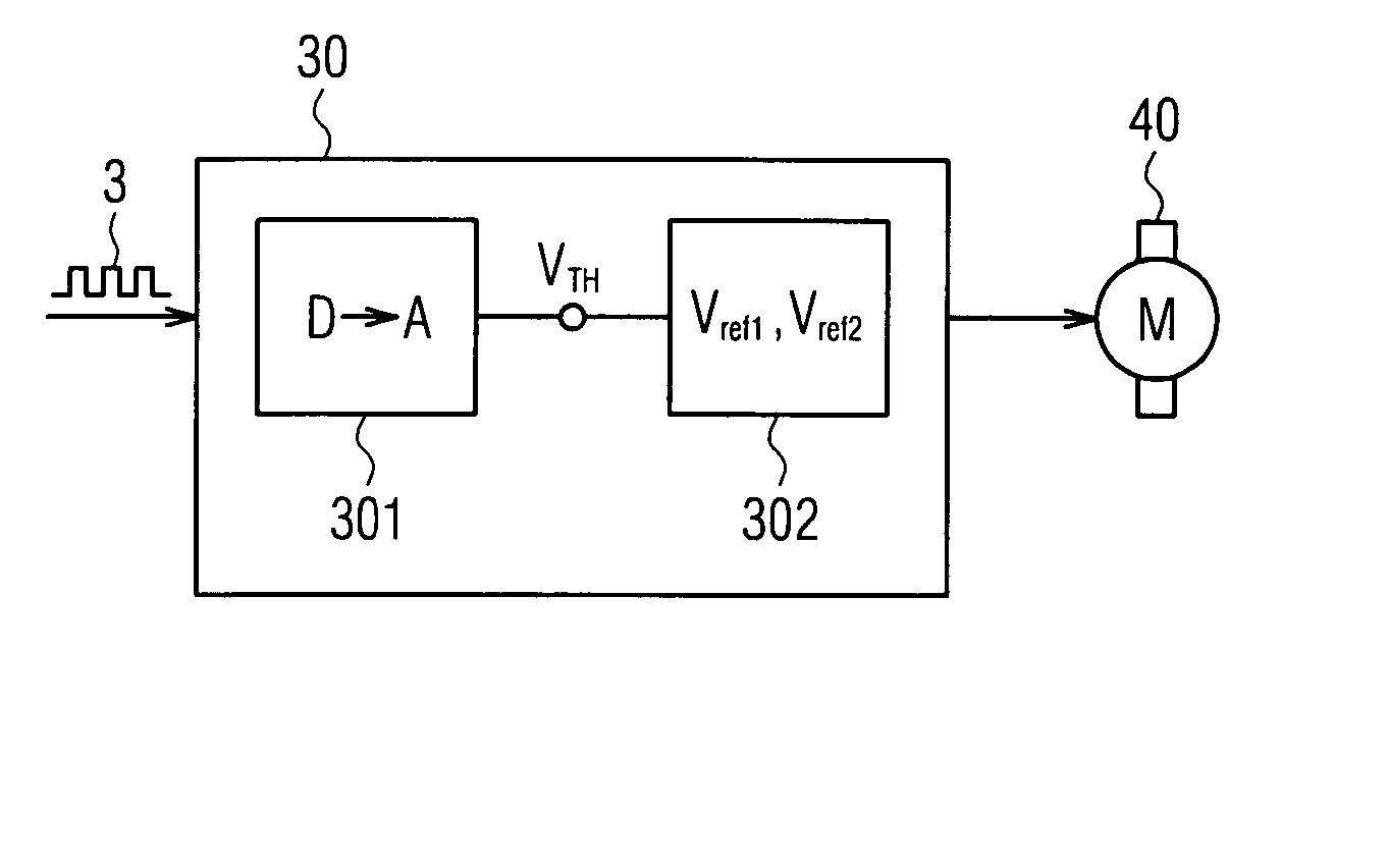
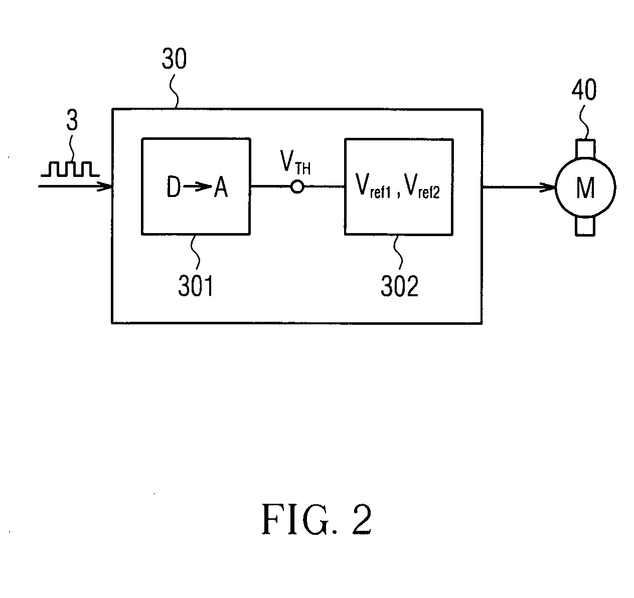
[0019] Referring to FIG. 2, a fan motor speed control circuit 30 in accordance with the invention comprises a digital / analog converting unit 301 and a driving unit 302. The digital / analog converting unit 301 is used for converting an inputted PWM digital signal 3 into an analog signal such as a voltage signal. The driving unit 302 takes the analog signal and compares it with two predetermined voltages Vref1 and Vref2 set by the driving unit. After that, a digital signal representing the comparison result is used to control the rotation speed of the fan motor 40.

[0020] The fan motor speed control circuit according to one embodiment of the invention is shown in FIG. 3A. In this embodiment, a digital / analog converting circuit 22 is employed as a digital / analog converting unit, and a drive IC 23 is employed as a driving unit. In this embodiment, the digital / analog converting circuit 22 is mainly composed of a transistor 221, a diode 222, a capacitor 223, and a plurality of resistors 22...


PUM


Abstract

A fan motor speed control circuit is disclosed. The circuit includes a digital/analog converting unit and a driving unit. The digital/analog converting unit takes charge of receiving a pulse width modulation (PWM) signal and converting it into a voltage signal. The driving unit is connected with the digital/analog converting unit in series for receiving the voltage signal, while the driving unit provides a first predetermined voltage level and a second predetermined voltage level as references. The fan motor is kept to run with a low constant rotation speed when the voltage signal level is higher than the first predetermined voltage level, with a full constant rotation speed when the voltage signal level is lower than the second predetermined voltage level, and with a variable rotation speed when the voltage signal level is lower than the first predetermined voltage level and higher than the second predetermined voltage level.

Description

BACKGROUND OF THE INVENTION [0001] This invention relates to a rotation speed control circuit, and more particularly to a fan motor speed control circuit. DESCRIPTION OF RELATED ART [0002] With respect to fan motor speed control techniques, it is well known that people skilled in the art often uses a control circuit being composed of various type of transistors and driving integrated circuit (IC) chips, and an external driving signal for the control circuit, such as a pulse width modulation (PWM) signal, to control the rotation speed of a fan motor. [0003] Referring to FIG. 1A, in a conventional fan motor rotation speed control technique, an external pulse width modulation (PWM) signal 3 is mainly used to drive a bipolar transistor 2 and a drive IC 5, in order to control the terminal voltage of a stator coil I representing the fan motor (not shown). In addition, a Hall element 4 is used to detect the magnetic polarity of a rotor of a fan motor, in order that the current direction of...

Claims


Application Information

Patent Timeline
IPC IPC(8): F04D27/02H02P6/08H02P6/06H03K17/60
CPCF04D27/004Y02B30/70
Inventor HUANG, WEN-SHITSAI, MING-SHILIU, CHENG-CHIEHHSIEH, TSUNG-JUNGHUANG, YUCH-LUNG
Owner DELTA ELECTRONICS INC
Why Eureka
Try Eureka