Perpendicular magnetic recording medium

a magnetic recording medium and perpendicular technology, applied in the field of perpendicular magnetic recording medium, can solve the problems of inability to achieve good recording quality, easy occurrence of thermal fluctuation error, disadvantages of in-plane magnetic recording system, etc., and achieve the effect of higher recording surface density

Inactive Publication Date: 2005-01-27
WESTERN DIGITAL TECH INC
View PDF12 Cites 71 Cited by
  • Summary
  • Abstract
  • Description
  • Claims
  • Application Information

AI Technical Summary

Benefits of technology

[0019] It is a first object of this invention to provide a perpendicular magnetic recording medium comprising a recording layer excellent in perpendicular orientation so as to achieve a higher recording surface density.
[0020] It is a second object of this invention to provide a magnetic recording medium comprising a soft magnetic layer formed between a substrate and a recording layer and prevented from degradation in perpendicular orientation of the recording layer so as to achieve a higher recording surface density.
[0021] It is a third object of this invention to provide a perpendicular magnetic recording medium capable of achieving a higher recording surface density at a low cost.

Problems solved by technology

However, the in-plane magnetic recording system is disadvantageous in the following respect.
Specifically, in case where crystal grains in the magnetic recording layer are reduced in size in order to carry out information recording at a high recording surface density such as 60 Gbit / inch2, an influence of a demagnetizing field between neighboring crystal grains is increased so that a good recording quality may not be achieved.
This results in easy occurrence of a thermal fluctuation error due to thermal magnetic aftereffect.
If the thermal fluctuation error is significant, recording magnetization is attenuated with lapse of time.
Eventually, recorded information can not normally be reproduced.
Disadvantageously, however, formation of the soft magnetic layer inhibits the perpendicular orientation of the recording layer.
In case where the structure of the recording layer of the magnetic disk is substantially changed in order to adopt the perpendicular magnetic recording system instead of the in-plane magnetic recording system as described above, a development cost and a production cost are drastically increased as compared with the magnetic disk of the in-plane magnetic recording system already widespread in the market.
Therefore, an inexpensive magnetic disk may not be supplied.
Further, if it is necessary to more strictly control the perpendicular orientation during deposition of the recording layer as described above, the production cost of the perpendicular magnetic recording disk will further be increased.

Method used


Image

  • Perpendicular magnetic recording medium
  • Perpendicular magnetic recording medium

Examples


example 1

[0090] In Example 1, a perpendicular magnetic recording medium as a magnetic disk was produced in the following manner. An amorphous aluminosilicate glass was formed into a disk-like shape by direct pressing to produce a glass disk. The glass disk was successively subjected to grinding, polishing, and chemical strengthening to obtain a nonmagnetic flat disk substrate comprising a chemically strengthened glass disk.

[0091] The surface roughness of a principal surface of the disk substrate was measured by an atomic force microscope (AFM). As a result, the substrate had a flat and smooth surface profile given by Rmax of 4.8 nm and Ra of 0.42 nm. Herein, the surface roughness Rmax is defined in Japanese Industrial Standard JIS B0601 as a maximum height representative of a difference between a highest point and a lowest point of the surface and described, for example, in U.S. Pat. No. 6,544,893B2. The surface roughness Ra is also defined in Japanese Industrial Standard JIS B0601 as an ar...

example 2

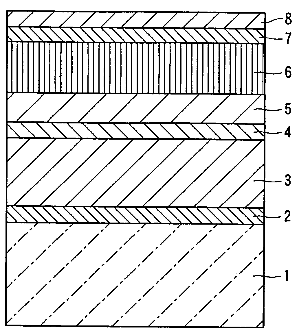
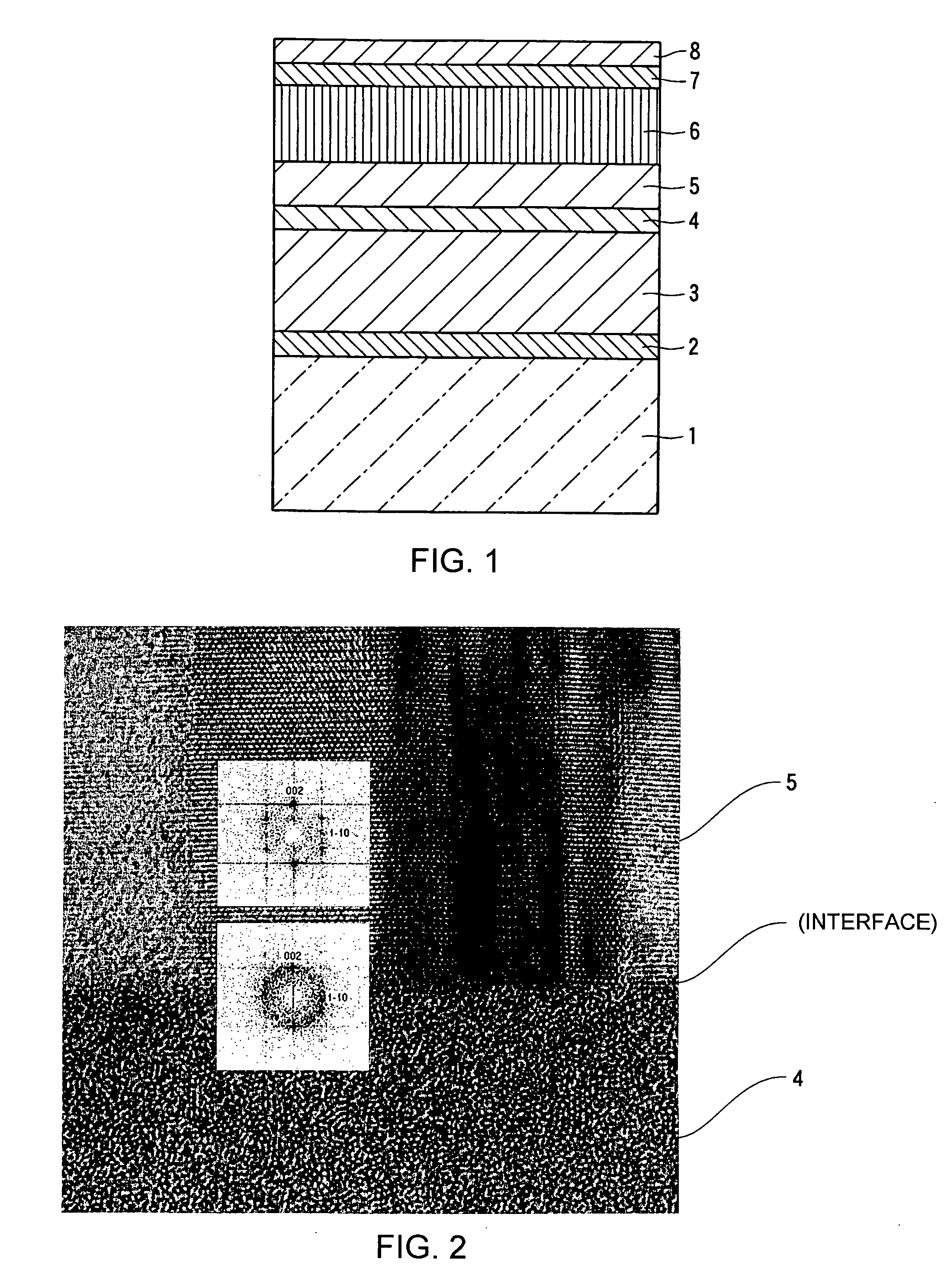
[0106] In Example 2, on a substrate similar to that in Example 1, the following layers were successively deposited. As shown in Table 1, the soft magnetic underlayer 3 was an amorphous (noncrystalline) cobalt-tantalum-zirconium (Co—Ta—Zr) (Co: 88 at %, Ta: 7 at %, Zr: 5 at %) alloy layer. The first nonmagnetic underlayer 4 was a nonmagnetic amorphous nickel-tantalum (Ni—Ta) (Ni: 45 at %, Ta: 55 at %) alloy layer. The second nonmagnetic underlayer 5 was a nonmagnetic ruthenium (Ru) metal layer having a hexagonal close packed (hcp) crystal structure. The perpendicular magnetic recording layer 6was a hard magnetic layer comprising a cobalt-chromium-platinum-boron (Co—Cr—Pt—(B) alloy (Co: 66 at %, Cr: 17 at %, Pt: 13 at %, B: 4 at %). The materials of other layers and the producing conditions were similar to those in Example 1.

[0107] The perpendicular magnetic recording medium had magnetic characteristics shown in Table 1. The coercive force (Hc) was equal to 4500 oersted, the squarene...

example 3

[0108] In Example 3, on a substrate similar to that in Example 1, the following layers were successively deposited. As shown in Table 1, the soft magnetic underlayer 3 was an amorphous (noncrystalline) cobalt-tantalum-zirconium (Co—Ta—Zr) (Co: 88at %, Ta: 7 at %, Zr: 5 at %) alloy layer. The first nonmagnetic underlayer 4 was a nonmagnetic amorphous chromium-nickel-tantalum (Cr—Ni—Ta) (Cr: 50 at %, Ni: 40 at %, Ta: 10 at %) alloy layer. The second nonmagnetic underlayer 5 was a nonmagnetic ruthenium (Ru) metal layer having a hexagonal close packed (hcp) crystal structure. The perpendicular magnetic recording layer 6 was a hard magnetic layer comprising a cobalt-chromium-platinum-silicon dioxide (Co—Cr—Pt—(SiO2)) alloy ((Co: 64 at %, Cr: 16 at %, Pt: 20 at %): 92 mol % —SiO2: 8 mol %). The materials of other layers and the producing conditions were similar to those in Example 1.

[0109] The perpendicular magnetic recording medium had magnetic characteristics shown in Table 1. The coer...


PUM

PropertyMeasurementUnit
diameteraaaaaaaaaa
diameteraaaaaaaaaa
diameteraaaaaaaaaa

Abstract

In a perpendicular magnetic recording medium which includes a substrate (1) of a nonmagnetic material, first and second nonmagnetic underlayers (4 and 5) formed on the substrate, and a perpendicular magnetic recording layer (6) formed on the first and the second nonmagnetic underlayers, the first nonmagnetic underlayer is made of an amorphous nonmagnetic metal material containing a metal element which forms a face-centered cubic (fcc) crystal structure by a simple substance. The second nonmagnetic underlayer is formed on the first nonmagnetic underlayer in contact with the first nonmagnetic underlayer and made of a nonmagnetic material containing a hexagonal close packed structure. The perpendicular magnetic recording layer is formed on the second nonmagnetic underlayer in contact with the second nonmagnetic layer.

Description

[0001] This application claims priority to prior Japanese application JP 2003-279861, the disclosure of which is incorporated herein by reference. BACKGROUND OF THE INVENTION [0002] This invention relates to a perpendicular magnetic recording medium to be loaded in a hard disk drive (HDD) of a perpendicular magnetic recording system. [0003] In recent years, following the advancement of the information society, various types of information processing apparatuses have been proposed. Further, information recording apparatuses for use in those information processing apparatuses have been proposed also. In order to achieve a smaller size and a higher performance of the information processing apparatuses, the information recording apparatuses are required to have a greater information recording capacity and a higher recording density. [0004] As one of the information recording apparatuses, there is known a magnetic recording apparatus, such as a hard disk drive (HDD), using a magnetic dis...

Claims


Application Information

Patent Timeline
Patent Type & Authority Applications(United States)
IPC IPC(8): G11B5/65G11B5/667G11B5/738G11B5/73
CPCG11B5/7325G11B5/667G11B5/73921G11B5/737
Inventor KIM, KONGOSAKABE, KINOBUHORIKAWA, JUNICHI
Owner WESTERN DIGITAL TECH INC
Why Eureka
Try Eureka