

Process for recovery of 6-aminopenicillanic acid from an aqueous discharge stream
a technology of aqueous discharge and process, applied in biocide, peptide/protein ingredients, organic chemistry, etc., can solve the problems of significant yield loss, method that has proved to be impractical, solvent outweigh any benefit in increasing yield
- Summary
- Abstract
- Description
- Claims
- Application Information
AI Technical Summary
Benefits of technology
Problems solved by technology
Method used
Image

Examples
example 1
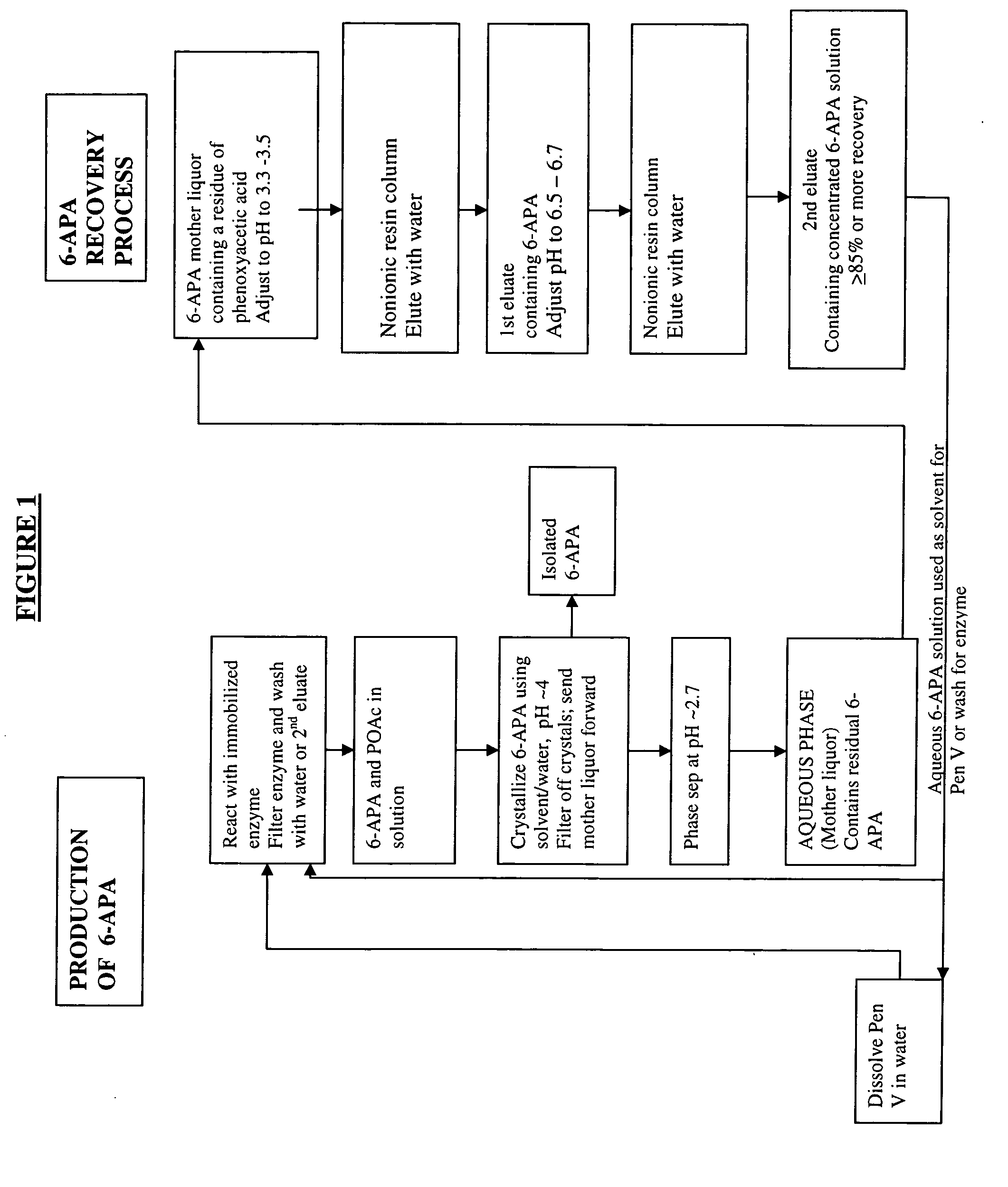
Preparation of a Solution of 6-APA
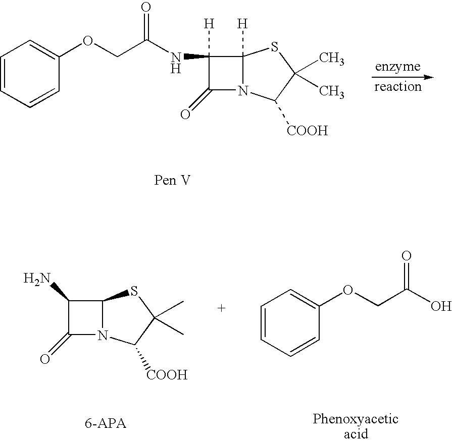
A solution of Penicillin V in water at pH 8.2 was treated with immobilized pen V amidase enzyme. The pH was maintained at 8.2 by addition of ammonium hydroxide until the penicillin V was converted to 6-APA. The resulting solution of 6-APA (7-8% w / v) was then filtered to remove the enzyme. The enzyme was washed with water, and the combined 6-APA solution and wash was carbon treated to remove color. The carbon was removed by filtration and washed with water. The 6-APA filtrate and wash were combined for the crystallization step.
example 2
Crystallization of 6-APA
At 20-25° C., one-half volume of butyl acetate was added to the aqueous 6-APA solution formed, for example, according to Example 2 and with vigorous stirring, the pH was slowly reduced to pH 3.9 with concentrated sulfuric acid. The resulting crystal slurry was maintained at pH 3.9 for 20 minutes. The crystals were then collected on a filter and washed with water and butyl acetate, then dried at 45-50° C. in vacuo. The loss in the aqueous mother liquor was ˜3-4 g / L (˜5-6% yield).
example 3
The pH of the two-phase mother liquor from Example 2 was lowered to pH 2.7 with concentrated sulfuric acid. The butyl acetate layer was separated off and the aqueous layer was retained containing ˜3-4 g / L 6-APA. This was used as the input to the mother liquor recovery process.
PUM
| Property | Measurement | Unit |
|---|---|---|
| pH | aaaaa | aaaaa |
| solubility | aaaaa | aaaaa |
| weight | aaaaa | aaaaa |
Abstract
Description
Claims
Application Information