
Influence of engine parameters on condensation protection strategies

Inactive Publication Date: 2005-01-27
DETROIT DIESEL CORP
View PDF15 Cites 54 Cited by
  • Summary
  • Abstract
  • Description
  • Claims
  • Application Information

AI Technical Summary

Benefits of technology

The present invention overcomes the above mentioned disadvantages by devising a new way to calculate IMT_Critical. This method is described with an equation that defines IMT_Critical as a function of a selected set of engine operating parameters although many different engine performance parameters affect IMT_Critical. The invention reduces the number of parameters being processed in the control and reduces the complexity of the processing taking those parameters affecting IMT_Critical. The method also provides an equation to be put in Engine Control Unit (ECU) for an accurate calculation of a prediction for IMT_Critical that may be employed in control algorithms.
This equation may be incorporated into the ECU (Electronic Control Unit) to calculate an IMT_Critical prediction. The condensation equation determines IMT_Critical based on the required parameters that may be populated, sensed or assumed values, the combined parameters providing an improved result without undue processing or excessive assumptions unrelated to actual conditions experienced by the equipment. Accordingly, when the measured intake manifold temperature in EGR mode is higher than IMT_Critical, the control may command the engine to operate in recirculation operating mode without harmful condensation at the intake manifold. This method is preferably applied only in steady state / cruising conditions of the vehicle due to the residence time required for condensation to occur.

Problems solved by technology

Condensation is a problem identified in engines using exhaust gas recirculation (EGR).
However, some of the influential conditions or parameters cannot be readily or economically sensed in the environment of equipment, particularly vehicles, in ambient conditions and modes of operation.
Alternatively, under protection may assume a low humidity so that EGR entry is enhanced to reduce emissions, but at the risk of reduced engine life.

Method used


Image

  • Influence of engine parameters on condensation protection strategies
  • Influence of engine parameters on condensation protection strategies
  • Influence of engine parameters on condensation protection strategies

Examples


Embodiment Construction

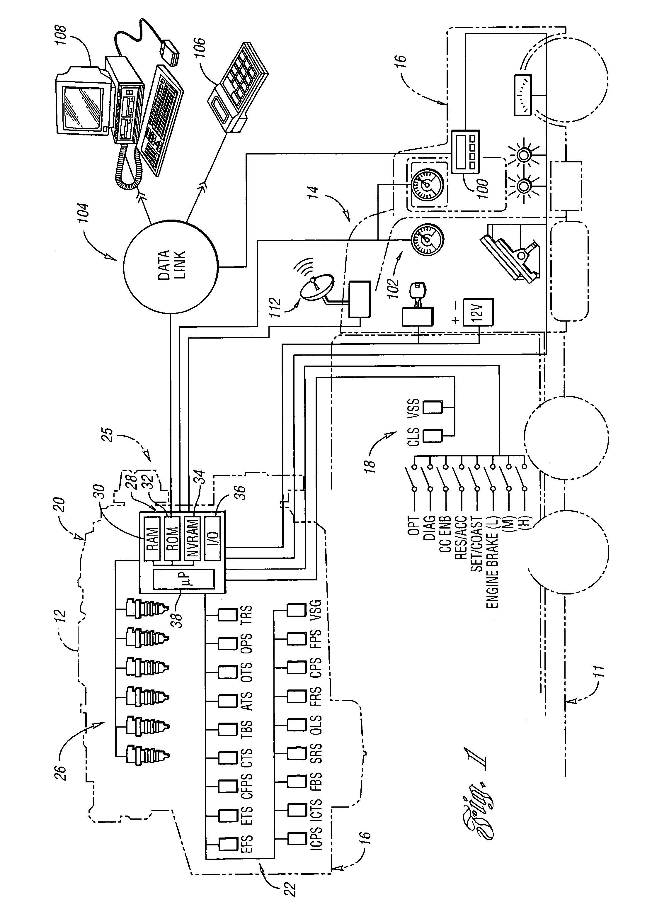
FIG. 1 is a perspective view of a compression-ignition, internal combustion engine 20 incorporating various features of engine control according to the present invention. As will be appreciated by those of ordinary skill in the art, engine 20 may be used in a wide variety of equipment 11 for applications including on-highway trucks, construction equipment, marine vessels, and stationary generators, among others. Engine 20 includes a plurality of cylinders disposed below a corresponding cover, indicated generally by reference numeral 12. In a preferred embodiment, engine 20 is a multi-cylinder compression ignition internal combustion engine, such as a 4, 6, 8, 12, 16, or 24 cylinder diesel engine, for example. Moreover, it should be noted that the present invention is not limited to a particular type of engine or fuel.

Engine 20 includes an engine control module (ECM) 28. ECM 28 communicates with various engine sensors and actuators via associated cabling or wires, indicated generall...


PUM


Abstract

A control and method for an internal combustion engine that includes an exhaust gas recirculation system to predict an intake manifold critical temperature (dew point) at which condensation would occur upon entry into exhaust gas recirculation. The control calculates the intake manifold critical temperature (IMT_Critical) as a function of predetermined, sensed or assumed values by processing an equation whose variables are occupied by the values. The control commands adjustments of exhaust gas recirculation operation in response to the calculation, preferably after the actual intake manifold temperature exceeds the IMT_Critical for a predetermined time.

Description

BACKGROUND OF THE INVENTION 1. Field of the Invention The present invention relates to compression ignition internal combustion engines including exhaust gas recirculation and variably operating between an exhaust gas recirculation (EGR) mode and a non-EGR mode, preferably known as boost mode, wherein an engine control monitors operating conditions and calculates a critical intake manifold temperature under operating conditions as a function of a selected set of influence factors to predict condensation, and when operating conditions would result in condensation in the intake manifold during EGR mode, operating the engine in the non-EGR mode. 2. Background Art Condensation is a problem identified in engines using exhaust gas recirculation (EGR). The hot exhaust gas from diesel engines includes a mixture of water vapor from the burnt fuel and ambient air. EGR engines recirculate a limited amount of exhaust gas back into the intake manifold to combust any unused fuel and byproduct...

Claims


Application Information

Patent Timeline
IPC IPC(8): F02D21/08F02D23/00F02D41/00F02M25/07
CPCF02D41/0007F02D41/005F02D41/0072F02D2200/0406Y02T10/47F02D2200/0418F02M25/0728F02M25/0754Y02T10/144F02D2200/0414F02M26/25F02M26/47Y02T10/12Y02T10/40
Inventor BHARGAVA, SAMEERRAMAMURTHY, RAVISHANKARVADUVA, LAURENTIU
Owner DETROIT DIESEL CORP
Features
  • Generate Ideas
  • Intellectual Property
  • Life Sciences
  • Materials
  • Tech Scout
  • Unparalleled Data Quality
  • Higher Quality Content
  • 60% Fewer Hallucinations
Learn More