Two-stroke internal combustion engine

a two-stroke, internal combustion engine technology, applied in the direction of machines/engines, mechanical equipment, cylinders, etc., can solve the problems of inability to cope with the expected increase in exhaust gas regulation, the influence of these poisonous components on environmental contamination cannot be ignored, and the inferiority of the two-stroke internal combustion engine in fuel consumption, etc., to promote the atomization effect of fuel, enhance combustion efficiency, and improve the effect of scavenging efficiency

Inactive Publication Date: 2005-02-03
KIORITZ
View PDF1 Cites 22 Cited by
  • Summary
  • Abstract
  • Description
  • Claims
  • Application Information

AI Technical Summary

Benefits of technology

[0018] In this case, since the cross-sectional area of the scavenging introducing passageway is made smaller than the cross-sectional area of the scavenging passageway (preferably, about ⅓) and at the same time, the scavenging inlet port is designed to be gradually narrowed (or contracted) concomitant with the descending movement of the piston, the degree of reduction in pressure and flow rate of the scavenging gas can be minimized even in the latter stage of the descending stroke of the piston (in the vicinity of bottom dead center) as compared with the conventional engine where the scavenging inlet port which opens to the crank chamber is not contracted (i.e. the cross-sectional area of the scavenging inlet port is substantially the same as the cross-sectional area of the scavenging passageway). Because of this, it is possible to provide the scavenging gas to be blown out from the scavenging outlet port into the combustion actuating chamber with a predetermined thrusting force (pressure) and with a directionality until the scavenging stroke is completed (until the piston reaches the bottom dead center). Therefore, it is now possible to further promote the atomization effect of fuel during the scavenging stroke, to improve the scavenging efficiency (trapping efficiency) and to enhance the combustion efficiency. As a result, it is now possible to effectively minimize the poisonous components, in particular, the total HC, and additionally to enhance fuel consumption.
[0019] Further, since the scavenging introducing passageway is provided by simply forming a cut-out portion in the form of parallel chamfering at the lower external peripheral wall (skirt portion) of the piston, it is no longer required to separately prepare parts or to greatly modify the conventional engine, thus rendering the present invention highly advantageous in terms of manufacturing cost.
[0020] Additionally, in the case of a two-stroke internal combustion engine, fuel (gasoline) is usually mixed with lubricating oil before use, so that the fuel / lubricating oil mixture in the air / fuel mixture that has been introduced into the crank chamber is subjected to the effect of centrifugal separation especially on the occasion of the high-speed revolution of the engine, resulting in the separation of much of the fuel / lubricating oil mixture from the air component, thus allowing the fuel / lubricating oil mixture to adhere onto the inner wall of the crank chamber. In this case, since the cross-sectional area of the scavenging inlet port (the aforementioned scavenging introducing passageway) is made relatively narrow, the lubricating oil is permitted to easily separate from the fuel component prior to the introduction of the air / fuel mixture into the scavenging passageway, thus permitting much of the lubricating oil to leave in the crank chamber. Therefore, even if the supply flow rate of fuel (the fuel / lubricating oil mixture) is reduced (i.e. even if the air / fuel mixture is made more lean), it is possible to secure a sufficient quantity of lubricating oil required for lubricating the sliding components such as the piston, connecting rod, crank shaft, etc., thus preventing the lubricity of these components from being deteriorated.
[0021] Further, when the engine (of a portable working machine) is suddenly changed in attitude to a great extent (for example, when the body of chain saw is suddenly inclined upward) in the idling operation thereof, the fuel / lubricating oil mixture which remains as fluid in the crank chamber is permitted to excessively flow into the combustion actuating chamber through the scavenging passageway if the scavenging inlet port is disposed on the crank chamber side, thereby possibly resulting in the malfunction of engine such as by engine stall. In the case of the present invention, however, the fuel / lubricating oil mixture which is left as fluid in the crank chamber is barely permitted to flow at a stroke into the scavenging passageway, thereby making it possible to suppress the engine malfunction.

Problems solved by technology

Because of this, as compared with a four-stroke engine, the two-stroke internal combustion engine is not only inferior in fuel consumption but also disadvantageous in that a large amount of poisonous components such as HC (unburnt components in a fuel) and CO (incomplete combustion components in a fuel) are caused to be included into the exhaust gas.
Therefore, even if the two-stroke engine is small in capacity, the influence of these poisonous components on the environmental contamination cannot be disregarded.
Additionally, there are several problems as to how to cope with the regulation of exhaust gas which is expected to become increasingly severe in the future.
In particular, there are many difficulties as to how to cope with the minimization of HC (total HC) in exhaust gas.
Further, since the two-stroke internal combustion engine is designed to employ a blended fuel consisting of gasoline as fuel and lubricating oil, there are possibilities that the exhaust gas would be further contaminated due to this oil component, and that this oil component would be allowed to excessively flow into the combustion actuating chamber (though it may also be called combustion chamber, actuating chamber, cylinder chamber, etc., these chambers are generically referred to as a combustion actuating chamber in the present specification), thereby sometimes inviting operating malfunctions such as engine stalls.
Therefore, it is impossible to obtain a sufficient degree of scavenging effect as desired.
Rather, scavenging gas (air-fuel mixture) is more likely to be intermingled with the exhaust gas and hence it is impossible to sufficiently minimize the quantity of blow-by.

Method used


Image

  • Two-stroke internal combustion engine
  • Two-stroke internal combustion engine
  • Two-stroke internal combustion engine

Examples


Embodiment Construction

[0031] Next, various embodiments of the two-stroke internal combustion engine according to the present invention will be explained with reference to the drawings.

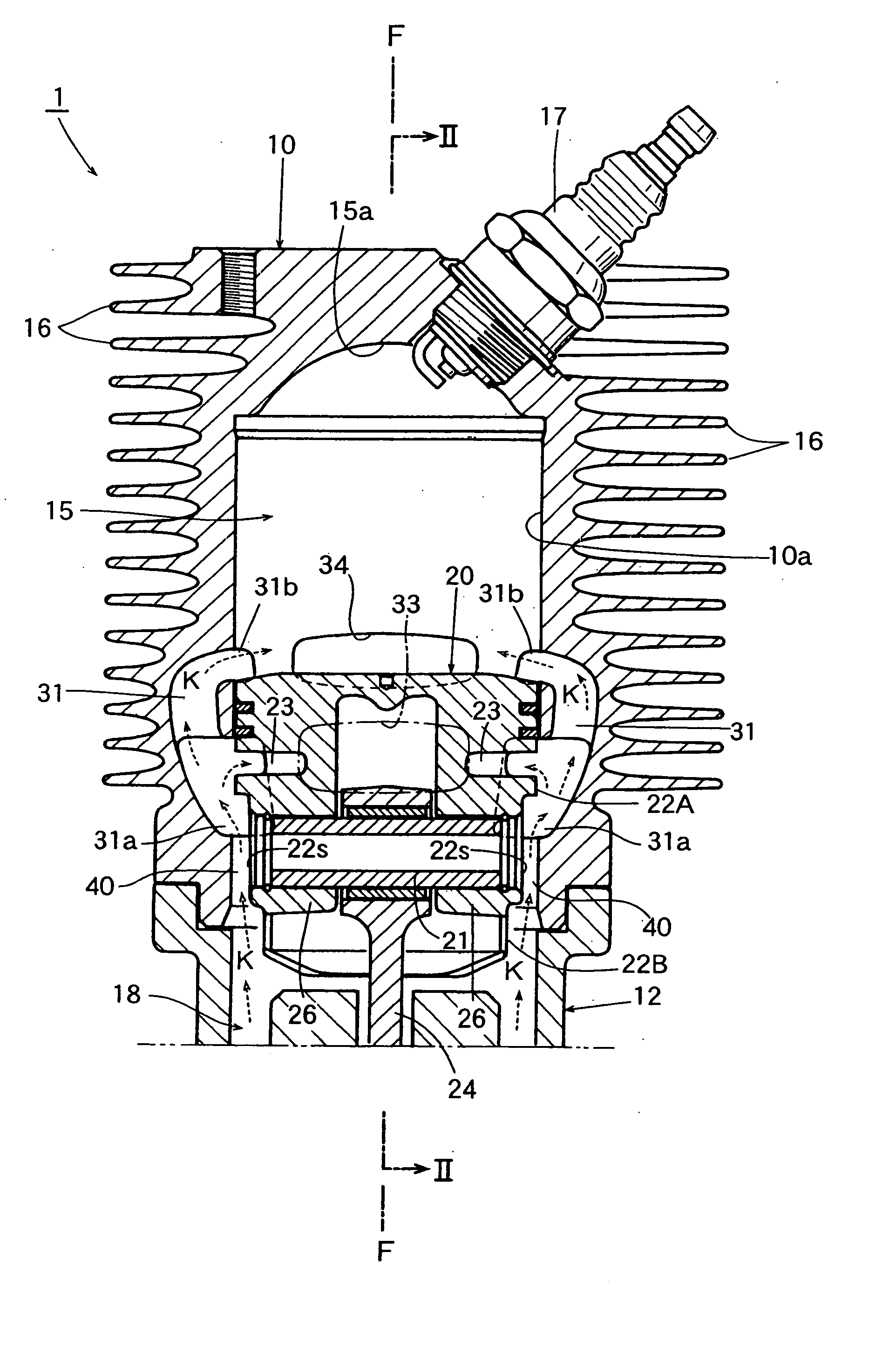
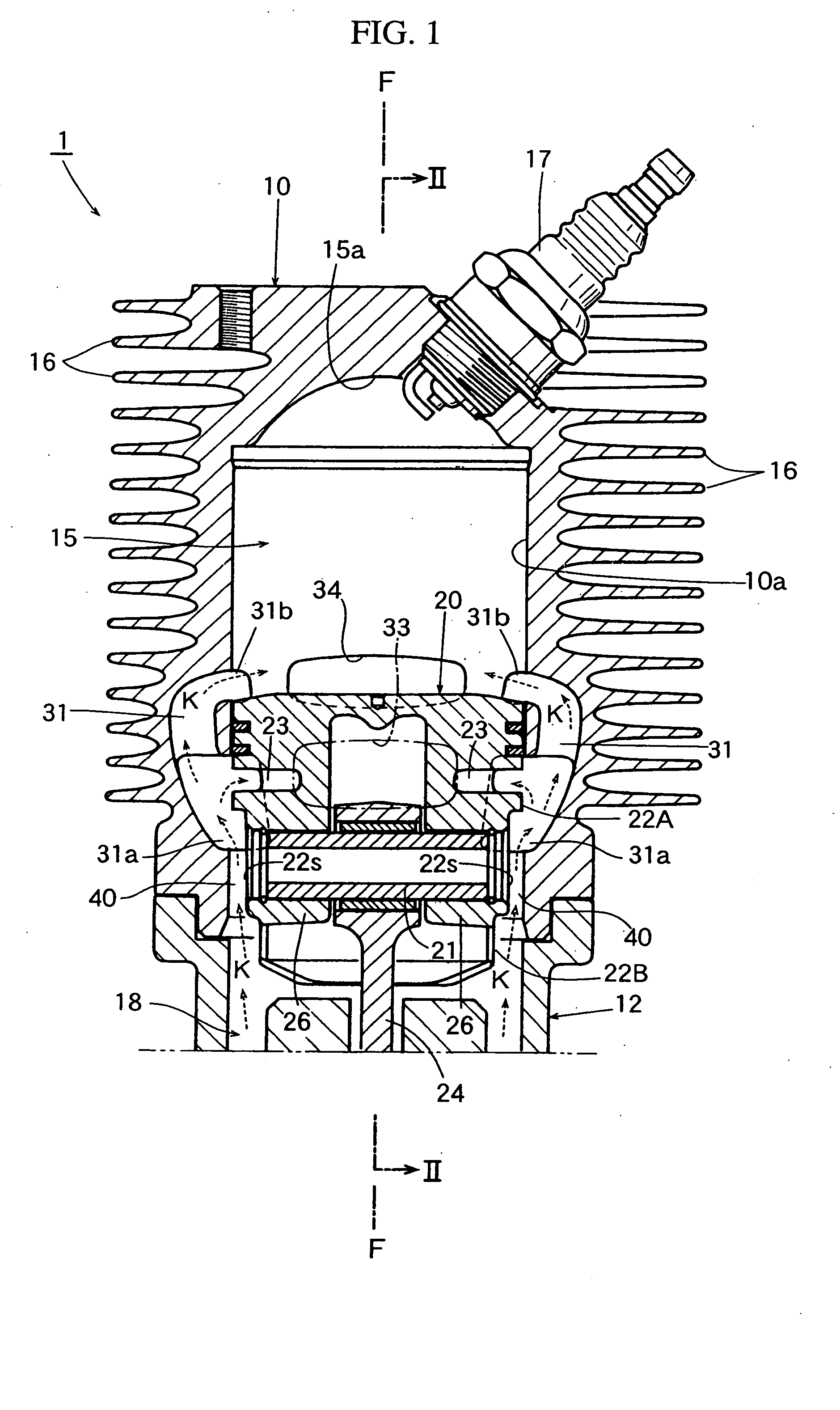
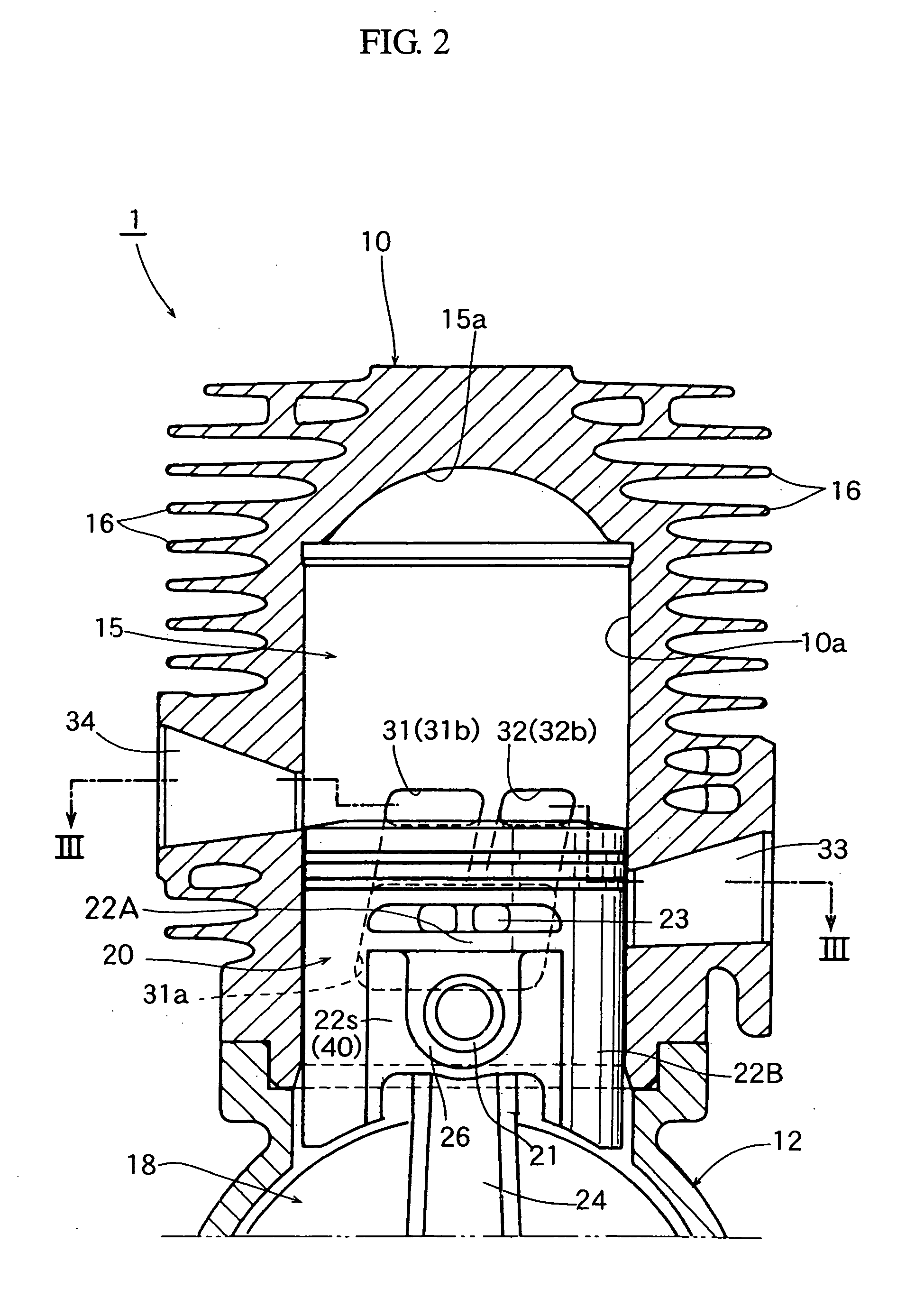
[0032]FIG. 1 is a longitudinal sectional view illustrating one embodiment of a two-stroke internal combustion engine according to the present invention; FIG. 2 is a cross-sectional view taken along the line II-II in FIG. 1; and FIG. 3 is a cross-sectional view taken along the line III-III in FIG. 2.

[0033] Referring to these FIGS., the two-stroke internal combustion engine 1 shown therein is formed of a small air-cooled two-stroke gasoline engine of the quaternary scavenging type, which is adapted to be employed in a portable working machine. This engine 1 comprises a cylinder 10 in which a piston 20 is fittingly inserted so as to enable it to reciprocatively move up and down, and a crankcase 12 which is disposed below the cylinder 10 and hermetically fastened to the cylinder 10. The crankcase 12 defines a crank chamber 18...


PUM


Abstract

A two-stroke internal combustion engine (1) is provided with one pair or plural pairs of C-shaped scavenging passageways (31, 32) of a reverse flow system where scavenging inlet ports (31a) as well as scavenging outlet ports (31b, 32b) are both opened to a cylinder bore (10a), wherein a scavenging introducing passageway (40) for introducing an air-fuel mixture (K) from a crank chamber (18) into the scavenging inlet ports (31a) is provided between the cylinder bore and the piston adapted to reciprocatively move up and down in the cylinder bore (10a), and an effective opening area of the scavenging inlet ports (31a) is gradually decreased due to the piston (20) in the course of descending stroke of the piston (20).

Description

BACKGROUND OF THE INVENTION [0001] The present invention relates to a two-stroke internal combustion engine which is suited for use for example in a portable power working machine, and in particular, to a two-stroke internal combustion engine which is capable of rendering combustion waste gas (exhaust gas) per se to be more completely cleaned and also capable of minimizing as much as possible the quantity of so-called blow-by or the quantity of air-fuel mixture to be discharged without being utilized for the combustion. [0002] An ordinary two-stroke gasoline engine which is conventionally used in a portable power working machine such as a chain saw or brush cutter is constructed such that an ignition plug is disposed at the head portion of the cylinder, and that an intake port, a scavenging port and an exhaust port, which are to be opened and closed by a piston, are provided so as to communicate with the cylinder bore (or provided in the inner peripheral wall of the cylinder). Accor...

Claims


Application Information

Patent Timeline
Patent Type & Authority Applications(United States)
IPC IPC(8): F02F3/00F02B25/14F02B25/16F02B75/02F02B75/16F02F1/22F02F3/24
CPCF02B25/14F02F1/22F02B2075/025F02B75/16
Inventor YAMAGUCHI, SHIROMATSUO, KENTAROKAMO, KEITATSUNODA, HIDEKAZU
Owner KIORITZ
Why Eureka
Try Eureka