Joystick-operated driving system

a technology of driving system and joystick, which is applied in the direction of mechanical control devices, manual control with single controlling member, instruments, etc., can solve the problems of significant effort expended in developing systems, drivers with certain physical disabilities may not be able to use their legs to operate the brake and accelerator pedal, and significant percentage of the driving population does not have full use of all of their limbs, etc., to achieve the greatest control, stable and reliable actuation of the brake pedal, and easy managemen

Inactive Publication Date: 2005-02-03
AHNAFIELD BRUCE
View PDF8 Cites 15 Cited by
  • Summary
  • Abstract
  • Description
  • Claims
  • Application Information

AI Technical Summary

Benefits of technology

[0015] In a feature of this embodiment, the slide block has a length that is less than the length of the slide member in the fore-aft direction. A top plate is disposed over the upward facing slot, with the top plate defining a housing slot in communication with the upward facing slot and a recess surrounding the housing slot. A larger slot cover is disposed within the recess and has a length that is less than a length of the recess. The larger slot cover also defines a first slot in communication with the housing slot, wherein the first slot has a length greater than the length of the slide block but less than the length of the housing slot. The assembly is completed by a smaller slot cover also disposed within the recess between the larger slot cover and the slide block. The smaller slot cover has a length less than the length of the larger slot cover but greater than the length of the first slot. The smaller slot cover further defines a second slot having a length slightly greater than the length of the slide block and greater than the length of the first slot, but less than the length of the larger slot cover. This combination of recess and slot covers provides a closure for the housing slot so that the slide member can slide within the body with minimal risk of introduction of dust and other contaminants into the slide channel that might foul the movement of the slide member or disturb the associated electrical components.
[0016] It is one object of the invention to provide a system that can be easily managed by a person having a physical disability that might otherwise prevent that person from operating a motor vehicle. One important object is to provide such a system that can provide that driver with the greatest ability to control the vehicle braking and acceleration.
[0017] A further object of the invention resides in features that make the system easy to retrofit to an existing vehicle, specifically with as little disruption to the driver-side area of the vehicle. Yet another object is accomplished by features that ensure stable and reliable actuation of the brake pedal, especially in an emergency braking condition.

Problems solved by technology

Unfortunately, a significant percentage of the driving population does not have full use of all of their limbs.
For instance, drivers with certain physical disabilities may be unable to use their legs to operate the brake and accelerator pedals.
Although no production vehicles have been developed to account for physically-impaired drivers, a significant amount of effort has been expended in developing systems that can be integrated into an existing vehicle control system to accommodate this driving population.
One problem faced by this and other vehicle control systems is that they require significant modification of the existing vehicle and are very difficult and time-consuming to install.
Another difficulty faced by some driving control systems is the “fail-safe” mode of operation of the system.
For instance, in some prior vehicle control systems, a failure of certain components of the system can compromise the ability of the driver to achieve a safe, controlled stop of the vehicle.

Method used


Image

  • Joystick-operated driving system
  • Joystick-operated driving system
  • Joystick-operated driving system

Examples


Embodiment Construction

[0038] For the purposes of promoting an understanding of the principles of the invention, reference will now be made to the embodiments illustrated in the drawings and described in the following written specification. It is understood that no limitation to the scope of the invention is thereby intended. It is further understood that the present invention includes any alterations and modifications to the illustrated embodiments and includes further applications of the principles of the invention as would normally occur to one skilled in the art to which this invention pertains.

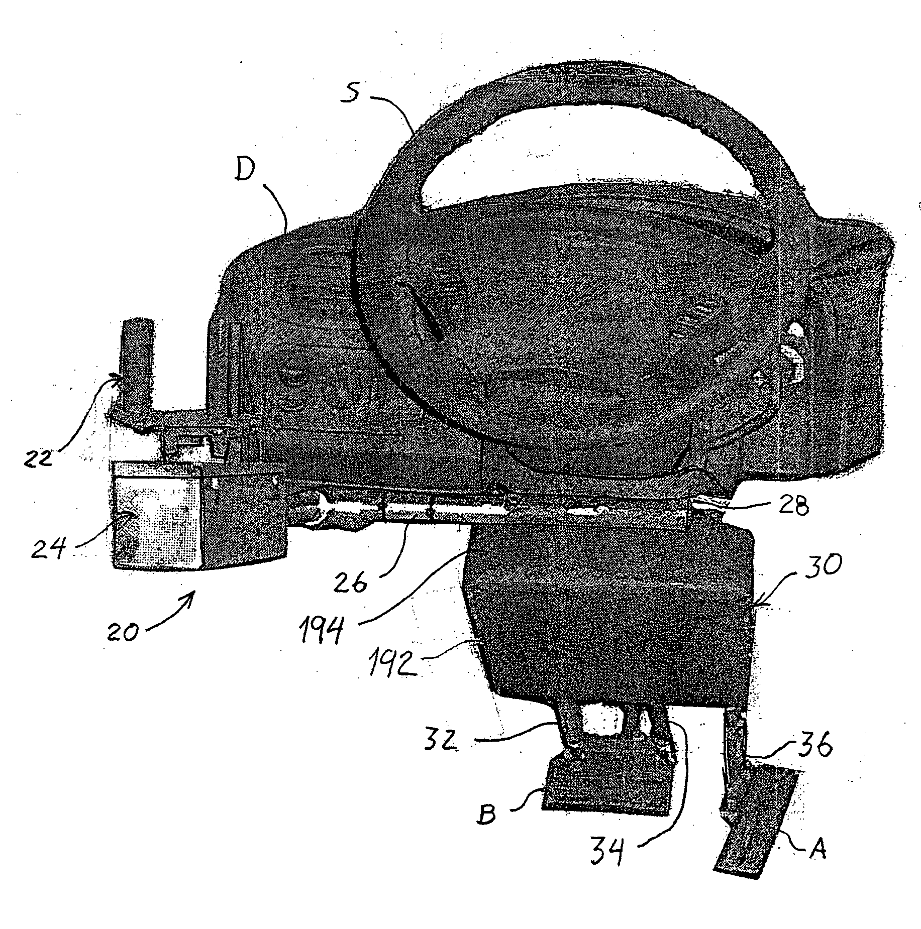
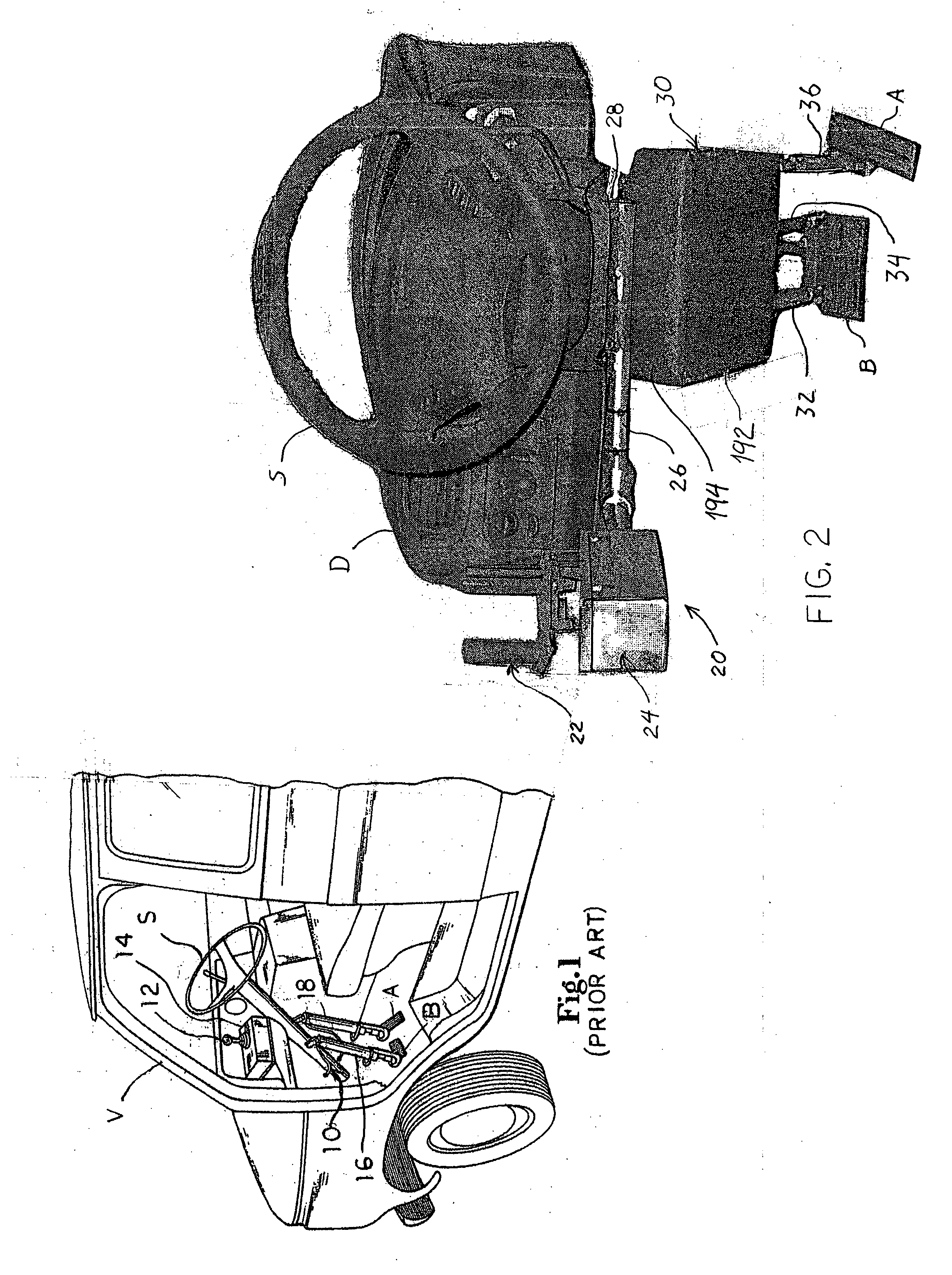
[0039] The present invention contemplates a vehicles control system for integration into an existing vehicle. In particular, the vehicle control system 20 of the present invention interfaces with the vehicle brake pedal B and accelerator pedal A, as shown in FIG. 2. Moreover, the control system 20 is supported relative to the column for the steering wheel S, and requires only minimal modification to the vehicl...


PUM


Abstract

A system for use by a physically impaired driver for controlling a vehicle includes an actuator assembly operably coupled to the pedals. The actuator assembly includes a pair of electrical motors operable through a rack and linkage arrangement to depress the brake pedal, and a third electric motor operable through a rack and linkage arrangement to depress the accelerator pedal. The actuator assembly is pivotably mounted above the pedals to pivot when the brake pedal is depressed. A joystick controller is mounted to the vehicle and includes a platform with a grip and arm supports. The joystick controller is operable in a fore-aft direction to control braking and acceleration, and can be tilted side-to-side to operate the vehicle turn signals. The joystick controller includes features for keeping the controller clear of dust and debris and for channeling wiring associated with the turn signals.

Description

BACKGROUND OF THE INVENTION [0001] The present invention relates to a system for controlling a motor vehicle, and particularly for operating the vehicle accelerator and brakes. This invention can be readily applied to vehicle control systems for physically impaired drivers. [0002] A conventional motor vehicle, such as an automobile, is designed for a driver having full and substantially unrestricted use of all of their limbs. The standard vehicle controls include a rotary operating steering wheel, a depressible brake pedal, and a depressible accelerator pedal. Of course, it is known that the steering wheel is operated manually, while the brake and accelerator pedals are operated by the driver's feet. Current production vehicles assume that the driver has full use of his / her hands and feet in order to operate these vehicle controls. [0003] Unfortunately, a significant percentage of the driving population does not have full use of all of their limbs. For instance, drivers with certain...

Claims


Application Information

Patent Timeline
Patent Type & Authority Applications(United States)
IPC IPC(8): B60K23/00B60K26/00B60K26/02G05G1/54
CPCB60K2741/003B60W30/18Y10T74/2022Y10T74/20012G05G1/54B60W2540/10B60W2540/12
Inventor AHNAFIELD, BRUCE
Owner AHNAFIELD BRUCE
Why Eureka
Try Eureka