

Control apparatus for synchronous motor
a control apparatus and synchronous motor technology, applied in the direction of motor/generator/converter stopper, electronic commutator, dynamo-electric converter control, etc., can solve the problems of the reliability of the sensor, and the inability to accurately predict the speed of the motor, so as to reduce the number of times of multiplication and division required for calculation and shorten the calculation time
- Summary
- Abstract
- Description
- Claims
- Application Information
AI Technical Summary
Benefits of technology
Problems solved by technology
Method used
Image

Examples
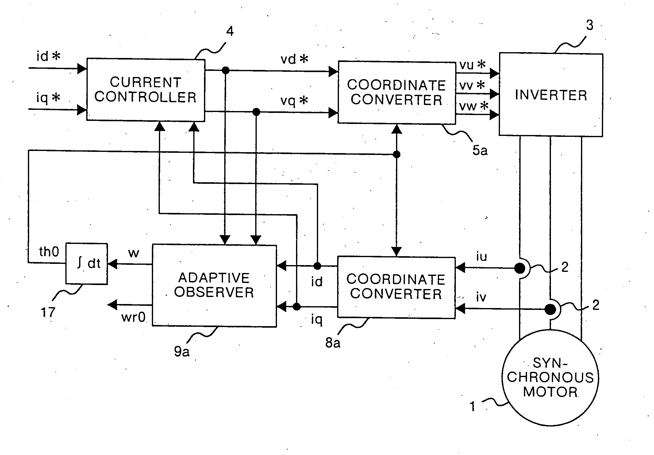
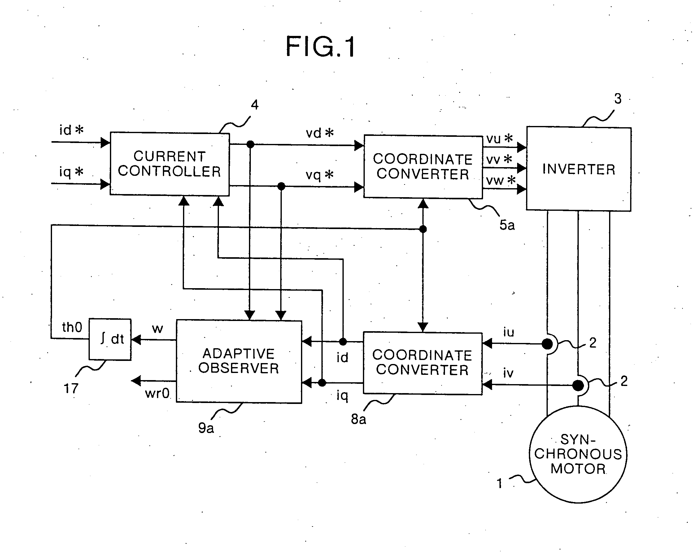
first embodiment
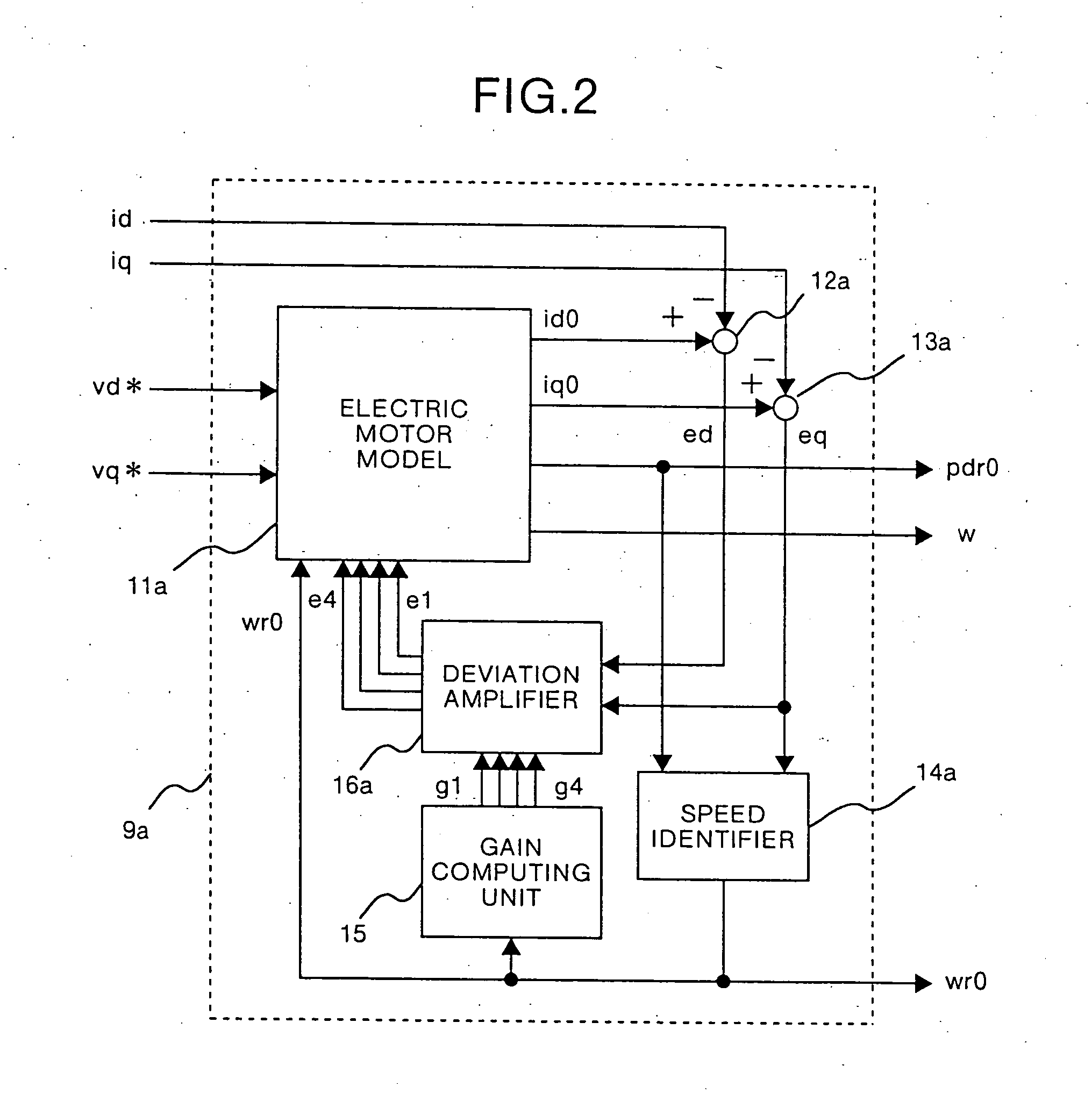
Derivation of an adaptive observer used in the present invention will be explained below. When electric motor models expressed by equations (4), (5), and (10) are converted into rotational biaxial coordinates (d-q axis) rotated at an arbitrary angular frequency w, the following equations (11) to (13) are obtained. ⅆ ⅆt(id0iq0pdr0pqr0)=(-RLw0wr0L-w-RL-wr0L0000w-wr000-w+wr00)(id0iq0pdr0pqr0)+(1L001L0000)(vd*vq*)-(e1e2e3e4)(11)wr0=(kp+kis)(ed·pqr0-eq·pdr0)(12)(e1e2e3e4)=(g1-g2g2g1g3-g4g4g3)(edeq)(13)
The equations (11) to (13) are satisfied on the rotational biaxial coordinate axis rotated at the arbitrary angular frequency w. Therefore, obviously these equations are also satisfied on the rotational biaxial coordinate axis rotated at the angular frequency w given by the following equation (14), w=wr0-e4pdr0(14)
Calculation of the angular frequency w given by the equation (14) corresponds to calculation in which the angular frequency w is calculated such that a q-axis component ...
second embodiment
In the first embodiment, the apparatus can be applied to a synchronous motor the inductance of which has no salient-pole properties. However, the apparatus cannot be directly applied to the synchronous motor which has salient-pole properties without any change to the apparatus. Therefore, in the second embodiment, a control apparatus for a synchronous motor which can be applied to a synchronous motor which has salient-pole properties will be explained.
As is well known, in the synchronous motor having salient-pole properties, an inductance in the direction of the rotor magnetic flux is different from an inductance in the direction perpendicular to the direction of the rotor magnetic flux, and therefore the inductance in the direction of the rotor magnetic flux is defined as Ld, and the inductance in the direction perpendicular to the direction of the rotor magnetic flux is defined as Lq in the following description.
In general, it is known that the following equation (19) holds o...
third embodiment
In the second embodiment, state variables of the adaptive observer 9b are handled as id0, iq0, pdr0, pqr0 (=0). However, the state variables may be handled as pds0, pqs0, pdr0, and pqr0. Reference symbols pds0 and pqs0 denote a d-axis component and a q-axis component of estimated armature reaction on a rotational biaxial coordinates defined by the following equation (31), (pds0pqs0)=(Ld00Lq)(ids0iqs0)(31)
When the equation (31) is substituted into the equations (20) to (22), the following equations (32) to (35) are obtained, ⅆⅆt(pds0pqs0pdr0)=(-RLdw0-w-RLq-wr0000)(pds0pqs0pdr0)+(32) (vd*vq*0)-(f1f2f3) w=wr0-f4pdr0(33)(f1f2f3f4)=(h11h12h21h22h31h32h41h41)(edeq)(34)(id0iq0)=(1Ld0001Lq0)(pds0pqs0pdr0)(35)where h11=Ld g11, h12=Ld g12 h21=Lq g21, h22=Lq g22 h31=g31, h32=g32 h41=g41, h42=g42
The configuration of the third embodiment merely uses an adaptive observer 9c in place of the adaptive observer 9a in FIG. 1. FIG. 6 is a diagram which shows the conf...
PUM
 Abstract
Description
Claims
Application Information