Supercharge Your Innovation With Domain-Expert AI Agents!

Rotational frequency detector system

a detector system and rotational frequency technology, applied in the field of rotational frequency detector systems, can solve the problems of small frequency step size produced by the vco, overwork of the charge pump requiring a higher speed and more complex design of the charge pump, and the frequency up or down signal produced by the prior art rfds is very small, so as to reduce the acquisition time, eliminate false locking, and increase the operating range of normalized frequency errors.

Active Publication Date: 2005-02-03
ANALOG DEVICES INC
View PDF3 Cites 2 Cited by
  • Summary
  • Abstract
  • Description
  • Claims
  • Application Information

AI Technical Summary

Benefits of technology

This patent describes an improved rotational frequency detector system that can accurately detect the frequency of a clock signal and adjust it to match the frequency of a data signal. The system uses a step control system and a step clock to generate fixed pulse widths for frequency up and down signals. This eliminates the need for a recovered clock and ensures consistent results regardless of variations in the incoming data. The system also provides controlled and predetermined pulse widths for the frequency up and down signals, and reduces acquisition time and residual frequency errors. Overall, this system provides a more accurate and efficient way to detect and adjust the frequency of a clock signal.

Problems solved by technology

The result is the pulse width of the frequency up and frequency down signals generated by prior art RFDs also varies directly with the changes in N. Therefore, at low values of N, the pulse width of the frequency up or frequency down signals produced by these prior art RFDs is very small which overworks the charge pump requiring a higher speed and more complex design of the charge pump.
Moreover, the resulting narrow pulse width frequency up signals and frequency down signals applied to the charge pump result in a very small frequency step size produced by the VCO which increases acquisition time of the frequency locked loop (FLL).
Another drawback associated with prior art RFDs is that the operating range of the normalized frequency error of these RFDs is between −37% to +50%.
Although in some applications this is not a problem, as the circuit may be designed to be centered at the expected data frequency and varies little around that point, in other applications, such as wide-band applications, this is unacceptable.
Yet another drawback of conventional RFDs is that when the normalized frequency error is less than approximately −50% no output is produced which results in a condition that is indistinguishable from a true lock.
This can result in a false lock condition.

Method used


Image

  • Rotational frequency detector system
  • Rotational frequency detector system
  • Rotational frequency detector system

Examples


Embodiment Construction

[0042] Aside from the preferred embodiment or embodiments disclosed below, this invention is capable of other embodiments and of being practiced or being carried out in various ways. Thus, it is to be understood that the invention is not limited in its application to the details of construction and the arrangements of components set forth in the following description or illustrated in the drawings.

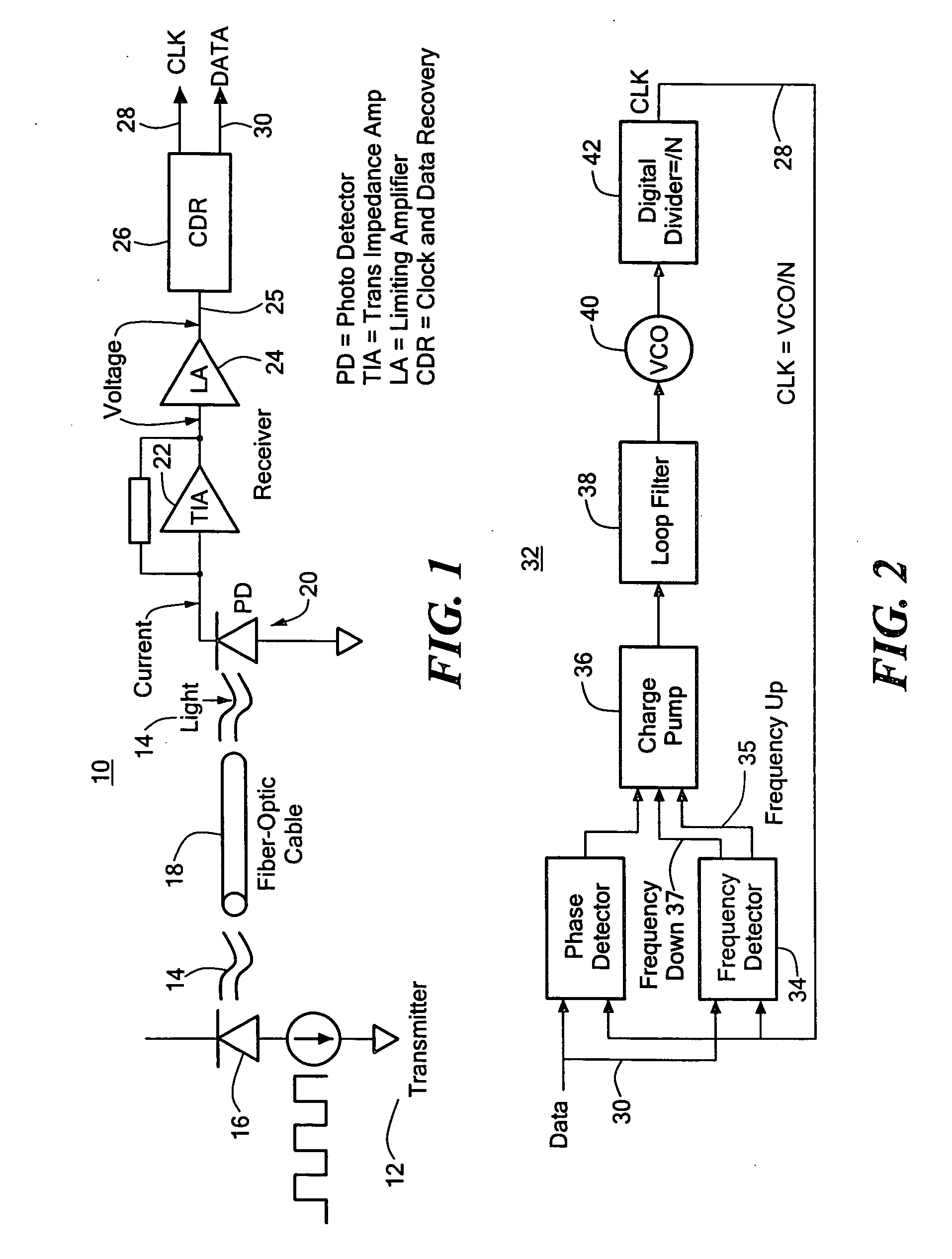
[0043] As discussed in the Background section above, fiber optic communications link 10, FIG. 1 typically includes transmitter 12 to transmit and direct light 14 emitted from laser diode 16 through fiber optic cable 18. At the receiving end of fiber optic cable 18 light 14 is detected by photodetector 20 which converts light 14 into an electrical current. The current is converted to a voltage by transimpedance amplifier 22 and then amplified by limiting amplifier 24. The limited and amplified signal on line 25 is then applied to clock and data recovery circuit 26 which extracts a clock si...


PUM


Abstract

A rotational frequency detector system including a rotational frequency detector responsive to a data signal and a clock signal. The rotational frequency detector is configured to compare the frequency of the clock signal to the frequency of the data signal to define frequency up and frequency down signals that adjust the frequency of the clock signal to be equal to the frequency of the data signal. A step control system is responsive to the rotational frequency detector and a step clock signal and is configured to define predetermined pulse widths for the frequency up and frequency down signals.

Description

RELATED APPLICATIONS [0001] This application claims priority of U.S. Provisional Application No. 60 / 490,649 filed Jul. 28, 2003, incorporated by reference herein.FIELD OF THE INVENTION [0002] This invention relates to an improved rotational frequency detector system typically employed in the frequency locked loop of a clock and data recovery circuit. BACKGROUND OF THE INVENTION [0003] A fiber optic communications link typically includes a transmitter to transmit and direct through a fiber optic cable light emitted from a laser diode. At the receiving end of the fiber optic cable the light is detected by a photo detector and converted into an electrical current. The current is converted to voltage by a transimpedance amplifier and then amplified by a limiting amplifier. The amplified voltage signal is applied to a clock and data recovery circuit which extracts a clock signal from the received data (i.e., a recovered clock signal) and acquires the frequency of the incoming data by com...

Claims


Application Information

Patent Timeline
Patent Type & Authority Applications(United States)
IPC IPC(8): H03D13/00H03L7/087H03L7/089H03L7/091H03L7/10H04L7/033
CPCH03D13/004H03L7/087H04L7/033H03L7/091H03L7/10H03L7/0891H03L7/113
Inventor DALTON, DECLAN M.DEVITO, LAWRENCE M.FERRISS, MARKMURRAY, PAUL
Owner ANALOG DEVICES INC
Features
  • R&D
  • Intellectual Property
  • Life Sciences
  • Materials
  • Tech Scout
  • Unparalleled Data Quality
  • Higher Quality Content
  • 60% Fewer Hallucinations
Learn More