Apparatus and method for automatic power control

a technology of automatic power control and apparatus, applied in the field of automatic power control apparatus, can solve the problems of medium-speed sampling device not being able to correctly sample the desired fpdo value, fpdo being likely to be slower, and only having a short steady-state time period, etc., to achieve stable power control, low response speed, and low cost

Inactive Publication Date: 2005-02-03
VOLVO LASTVAGNAR AB +1
View PDF12 Cites 26 Cited by
  • Summary
  • Abstract
  • Description
  • Claims
  • Application Information

AI Technical Summary

Benefits of technology

[0013] It is therefore a primary objective of the claimed invention to provide an automatic power control (APC) structure which can perform a stable power control for a high-speed and / or high-density optical recording apparatus and uses simply a low-speed and low-cost sampling device even though a front photodiode with a relatively low response speed is employed. The objective is primarily obtained through the use of a multi-pulse peak-hold device that compensates for the slow response speed of the front photodiode without requiring expensive additional hardware. It is to be understood that the multi-pulse peak-hold device of the claimed invention may obtain a maximum (the highest peak) voltage or the multi-pulse peak-hold device of the claimed invention may obtain a minimum (the lowest bottom) voltage. The need for the acquisition and holding of a peak or a bottom depends on the requirement of power level measurements in an APC structure and the use of either a peak-hold circuit or a bottom-hold circuit as applied in this disclosure and the appended claims is within the intended spirit of the present invention.

Problems solved by technology

In a high-speed and / or high-density optical recording application, the response speed ofthe FPD is likely to be slower than the modulation speed of the recording pulse of the LD.This results in the FPDO having only a short time period in steady state.
This problem is illustrated in FIG. 4 where even though the FPDO response reaches steady state near the end of an erase period, a medium-speed sampling device may fail to correctly sample the desired FPDO value.
Obviously, implementation of a high-response-speed sample and hold circuit is expensive.
In certain recording formatssuch as those using blue laser diodes, the recording pulse widths are so short that correctly sampling the FPDO is impossible for present hardware implementation technology under the constraint of reasonable costs.
Additionally, as the recording pulses get shorter and shorter, it is very likely that the response speed of the FPD is much slower than the modulation speed of the recording pulse of the LD.
As shown in FIG. 5, the FPDO cannot correctly reflect the optical power output of the LD.In this situation, the real output power cannot be measured correctly even with the use of a perfect sample and hold circuitregardless of cost.
The sampling problems in obtaining the write and bias power levels get worse for those optical disc formats with a multiple pulse train write strategies shown in FIG. 1 because the time duration in a modulated multiple pulse is several times less than during a write / erase period.
The FPDO will fluctuate, as shown in FIG. 5, and no sampling device can provide correct optical power measurement.
There may be no available sampling areas in the FPDO for the power level acquisitions of the erase, write, and bias periods.
Here, peak envelope signals outputted from the envelope detection devices are fed to standard sample and hold circuits, which in turn, output to the respective feedback control units.However, to reliably detect and reflect peaks (or bottoms) of the FPDO, the discharge time constant of a peak (or bottom) envelope detection device cannot be too large compared to that of the recording pulses of the LD.If the discharge time constant is too large, the peak (or bottom) envelope detection device may not correctly follow the FPDO.
Since the acquired power deviations result from the write strategy and temperature drifts simultaneously, the feedback controller unit will perform wrong power adjustments because of erroneously sensed FPDO variations resulting from write strategy.
Consequently, it will be difficult to stably compensate real power fluctuation resulting from the effect of temperature.

Method used


Image

  • Apparatus and method for automatic power control
  • Apparatus and method for automatic power control
  • Apparatus and method for automatic power control

Examples


Embodiment Construction

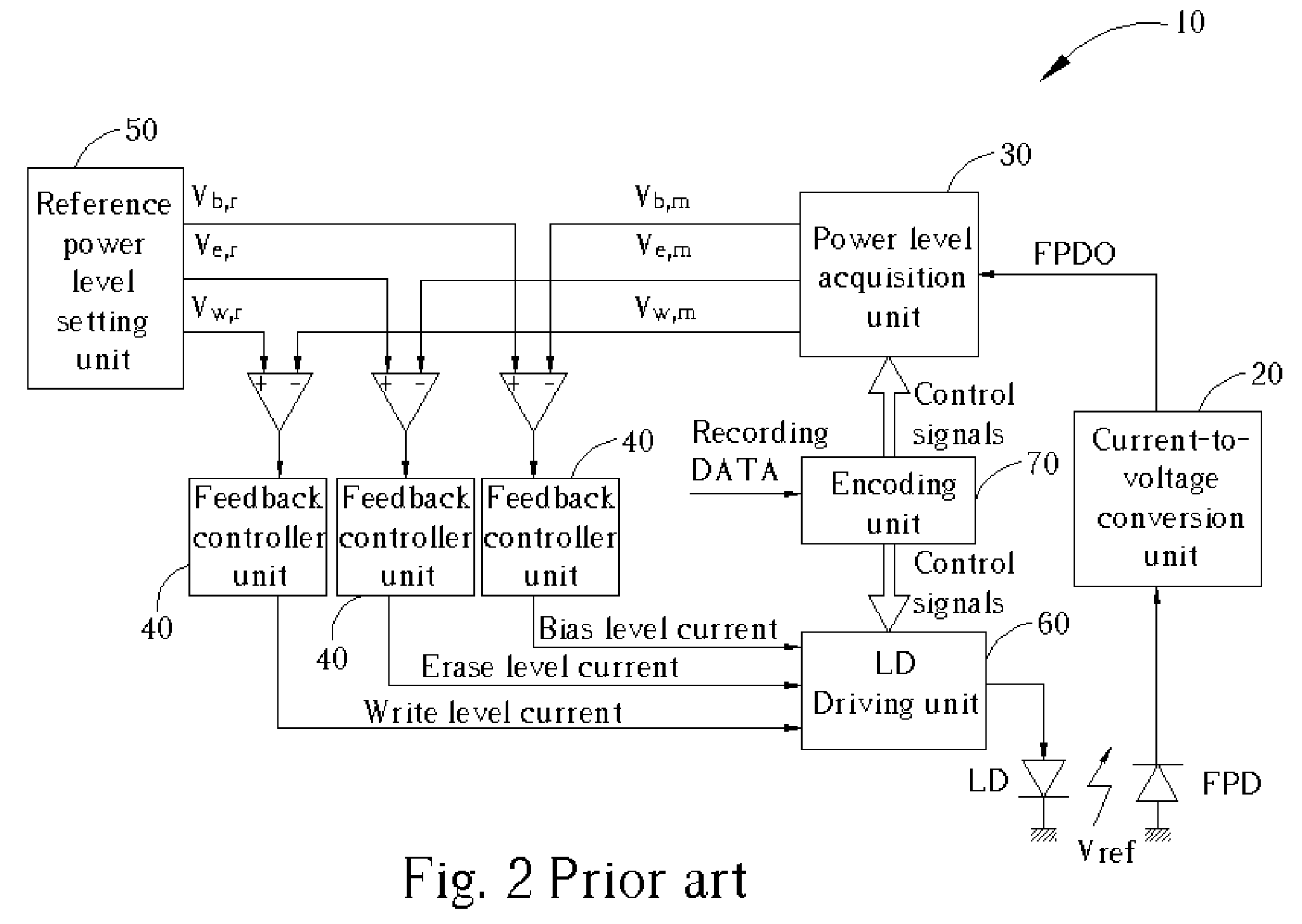
[0035] The present invention proposes a multi-pulse peak-hold device in a power level acquisition unit, instead of using a high-speed sample and hold circuit such as those frequently adopted in a conventional optical recording apparatus. FIG. 8 is a block diagram of the present invention if three power level controls are configured in an Automatic Power Control (APC) structure 110. Similar reference numerals are used for those components of the APC 110 that serve the same function as the corresponding components of the prior art APC 10. These functions have been previously described in this paper and will not be again elaborated on here. The obvious differencesin the present invention APC 110 from the prior art are the multi-pulse peak-hold (or bottom-hold) device 130 and the calibration gain 140 located in the output of the multi-pulse peak-hold (or bottom-hold) device 130thatis manifested in high-speed and / or high-density optical storage applications when a relatively low speed fr...


PUM

PropertyMeasurementUnit
optical output power levelaaaaaaaaaa
voltageaaaaaaaaaa
optical output poweraaaaaaaaaa

Abstract

An apparatus and method for automatic power control is disclosed. An optical recording apparatus utilizes a low-speed, peak-hold circuit to obtain and output a maximum of a front photodiode output signal during a predetermined window or plurality of windows of a total duration long enough to allow maximum peak-hold signal to stabilize. After stabilization, the maximum peak-hold signal is sampled and held in a sample and hold circuit. A reset then clears the signal and reinitializes the peak-hold circuit. In accordance with the difference between a reference voltageand the held peak-hold signal, a feedback controller unit outputs the required current level into a driving unit for producing desired recording pulses into a laser diode for recording information pits into an optical disc. A calibration gain may be used when, due to insufficient FPD response speed, the held signal is different than the real optical power output.

Description

BACKGROUND OF INVENTION [0001] 1. Field of the Invention [0002] The present invention relates to a laser-powercontrol apparatus employed in an optical recording device. More particularly, a power-control devicefor an optical disc recording system that controls the optical power stably during high-speed optical information recording even if using a relative low-speed front photodiode is disclosed. [0003] 2. Description of the Prior Art [0004] A laser diode is usually used as a light source in a conventional optical recording apparatus. It is well known that the optical power output of a laser diode varies greatly with changes in environmental temperature. Accordingly, it is necessary to compensatefor unwanted temperature-induced power fluctuations in the operation of laser diodes. A feedback control device for stabilizing the output power of a laser diode is called an automatic power control (APC) and is generallyutilized in a conventional optical recording apparatus. [0005] In order...

Claims


Application Information

Patent Timeline
Patent Type & Authority Applications(United States)
IPC IPC(8): G11B7/0045G11B7/125
CPCG11B7/1263G11B7/00456
Inventor HSU, HAN-WENCHU, CHIH-HSIUNGMA, PAO-PING
Owner VOLVO LASTVAGNAR AB
Why Eureka
Try Eureka