Processes and systems for making phosgene

a technology of phosgene and process, applied in the preparation of carboxylic acid halides, physical/chemical process catalysts, separation processes, etc., can solve the problem of less than the capacity of activated carbon to remove hsub>2/sub>s, sulfur deposits on the phosgene catalyst in the reaction chamber, sulfur deposits in downstream equipment, etc., to reduce the concentration of hydrogen sulfide

Inactive Publication Date: 2005-02-03
SABIC GLOBAL TECH BV
View PDF2 Cites 12 Cited by
  • Summary
  • Abstract
  • Description
  • Claims
  • Application Information

AI Technical Summary

Benefits of technology

[0003] Disclosed herein are a system and a process for producing phosgene. In one embodiment the process for producing phosgene comprises: introducing a carbon monoxide stream to a metal oxide impregnated activated carbon, reducing a hydrogen sulfide concentration in the carbon monoxide stream to produce a cleaned stream, wherein a cleaned stream hydrogen sulfide concentration is less than or equal to about 20 ppm, and reacting carbon monoxide in the cleaned stream with chlorine to produce phosgene.

Problems solved by technology

The capacity for activated carbon to remove H2S, however, is less than its capacity to remove most other sulfur compounds.
Several disadvantages occur as a result of the premature exhaustion of the activated carbon with respect to H2S removal.
One problem is that sulfur deposits on the phosgene catalyst in the reaction chamber.
Another problem is that deposits of sulfur foul the downstream equipment, such as the CO / Cl2 mixing area, the phosgene reactor, and the phosgene condenser.
In addition, there is loss of productivity because of the need to frequently interrupt the synthesis process in order to remove the activated carbon and regenerate or replace it.

Method used


Image

  • Processes and systems for making phosgene
  • Processes and systems for making phosgene
  • Processes and systems for making phosgene

Examples


example 1

Removal of Sulfur Compounds Using BPL® Activated Carbon Only

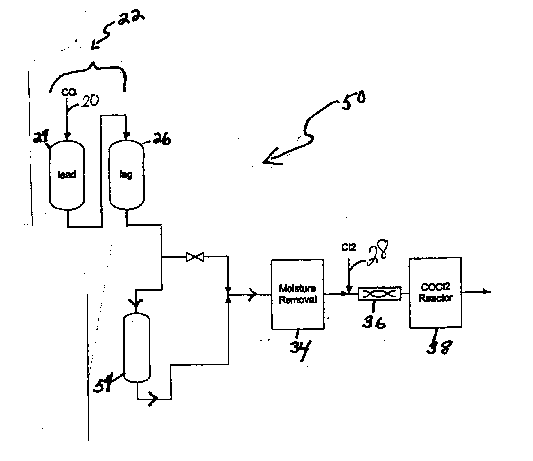
[0029] Referring to FIG. 1, a carbon monoxide gas stream comprising 4,630 ppm COS, 1,991 ppm CS2, and 118 ppm H2S, passed through the first sulfur removal unit (22); passing through both the lead position sub-unit (24) and then through the lag position sub-unit (26) at a rate of at 8,000 pounds per hour (lbs / hr). Both lead and lag sub-units included 30,000 lbs of non-MOI activated carbon composition as the sulfur removal composition, which removed COS and CS2 gases and some hydrogen sulfide gas from the carbon monoxide gas stream. After flowing through the lead and lag positions, the modified stream passed through the moisture removal unit (34) that reduced the water content of the modified stream to 1 ppm before passing mixing with chlorine in the mixer (36) and introduction to the reactor (38) where phosgene was produced.

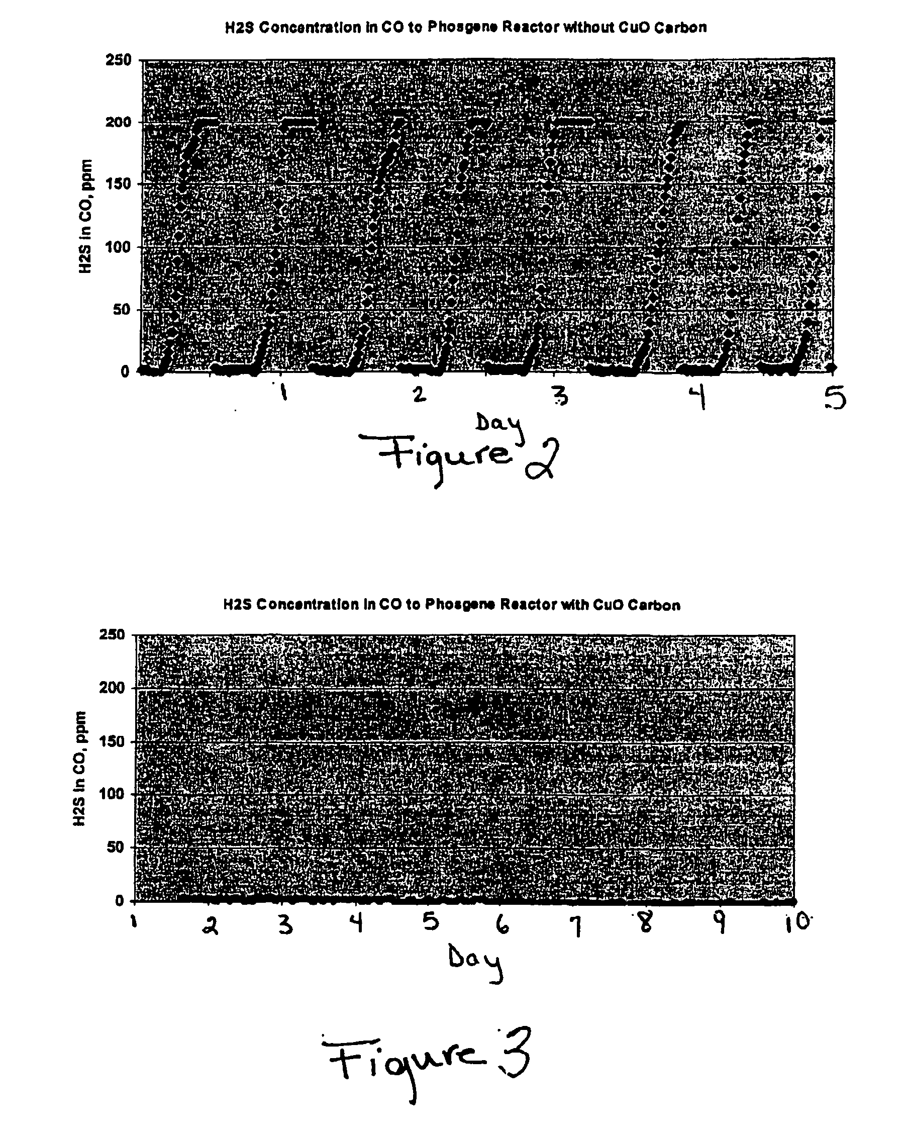
[0030]FIG. 2 graphically represents the hydrogen sulfide concentration in the modified stream at the...

example 2

Removal of Sulfur Compounds Using BPL® Activated Carbon Followed by a CuO-Impregnated Activated Carbon

[0031] The process in Example 1 was repeated with the difference being the use of a polishing bed; namely a CuO-impregnated activated carbon sulfur removal unit (54) disposed downstream of the sulfur removal unit (22). This sulfur removal unit (54) comprised 15,000 lbs CuO impregnated activated carbon (i.e., NUSORB FC).

[0032] A carbon monoxide gas stream comprising 4,630 ppm COS, 1,991 ppm CS2, and 118 ppm H2 S, passed through the first sulfur removal unit (22) comprising BPL® activated carbon; passing through both the lead position sub-unit (24) and then through the lag position sub-unit (26) at a rate of at 8,000 pounds per hour (lbs / hr). Both lead and lag sub-units included 30,000 lbs of non-MOI activated carbon composition as the sulfur removal composition, which removed COS and CS2 gases to produce a modified stream.

[0033] After flowing through the lead and lag positions, th...


PUM

PropertyMeasurementUnit
temperatureaaaaaaaaaa
pressureaaaaaaaaaa

Abstract

One process for producing phosgene comprises: introducing a carbon monoxide stream to a metal oxide impregnated activated carbon, reducing a hydrogen sulfide concentration in the carbon monoxide stream to produce a cleaned stream, wherein a cleaned stream hydrogen sulfide concentration is less than or equal to about 20 ppm, and reacting carbon monoxide in the cleaned stream with chlorine to produce phosgene.

Description

BACKGROUND OF THE INVENTION [0001] Gases originating from sulfur-containing organic compounds contain hydrogen sulfide, which should be removed prior to the use of the gases for a process such as the production of phosgene. Hydrogen sulfide can be partially removed from a gas by passing the contaminated gas over activated carbon, wherein the hydrogen sulfide is physically adsorbed into the pores of the activated carbon. The sulfur produced is adsorbed on the surface of the activated carbon, and eventually the activated carbon needs to be replaced or regenerated due to sulfur loading on its surface. [0002] Phosgene, COCl2, is produced by the reaction of carbon monoxide gas, CO, and chlorine gas, Cl2, over activated carbon. The carbon monoxide gas used in the reaction is typically produced from coke, and is usually contaminated by a number of sulfur compounds, including carbonyl sulfide (COS), carbon disulfide (CS2), and hydrogen sulfide (H2S). Before the carbon monoxide gas stream en...

Claims


Application Information

Patent Timeline
Patent Type & Authority Applications(United States)
IPC IPC(8): B01D53/14B01J21/18B01J23/72B01J23/94B01J38/12C01B32/80
CPCB01D53/1468B01J21/18B01J23/72B01J23/94C01B31/28B01J2219/00006B01J2219/0004B01J2219/00247B01J38/12C01B32/80Y02P20/584B01D53/14
Inventor BAGALA, FRANK M.LAPORTE, EDWARD L.MOORER, CURTIS R.ZHANG, CHUNJIE
Owner SABIC GLOBAL TECH BV
Why Eureka
Try Eureka