Direct fuel injection type internal combustion engine

a technology of direct injection and internal combustion engine, which is applied in the direction of machines/engines, mechanical equipment, electric control, etc., can solve the problems of inability to make an inability to make an air-fuel mixture in time, and limited engine operation conditions that enable the formation of appropriate stratified air-fuel mixtures, etc., to achieve suppressors or suppressors, the effect of increasing the amount of unburned hydrocarbons in the exhaust gas

Inactive Publication Date: 2005-02-10
NISSAN MOTOR CO LTD
View PDF10 Cites 11 Cited by
  • Summary
  • Abstract
  • Description
  • Claims
  • Application Information

AI Technical Summary

Benefits of technology

[0021] For improving the fuel consumption characteristic, the present invention proposes such a measure that after the fuel injection is carried out to produce an air-fuel mixture that is somewhat leaner than stoichiometric, an additional fuel injection is carried out at a timing just before the ignition by an ignition plug. With this measure, before the ignition, the air-fuel mixture placed around the ignition plug produces a condition that is appropriate for the fuel consumption characteristic.
[0022] It is said that when a fuel injection is carried out under a lower temperature condition of the engine, that is, under a condition wherein the temperature of engine cooling wate

Problems solved by technology

Thus, if for example the engine speed is increased, it tends to occur that formation of the air-fuel mixture is not made in time.
Accordin

Method used


Image

  • Direct fuel injection type internal combustion engine
  • Direct fuel injection type internal combustion engine
  • Direct fuel injection type internal combustion engine

Examples


Embodiment Construction

[0037] In the following, the present invention will be described in detail with reference to the accompanying drawings.

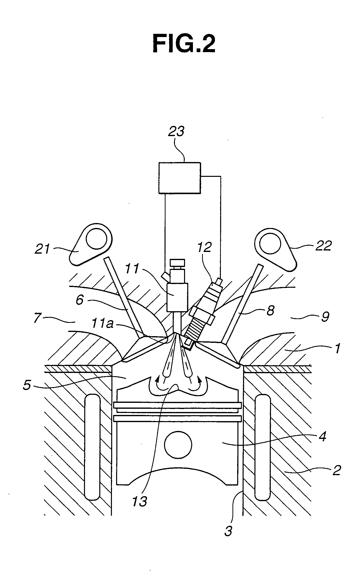
[0038] Referring to FIG. 2, there is shown a direct fuel injection type internal combustion engine of the present invention.

[0039] As shown, the engine generally comprises a cylinder head 1 with intake and exhaust ports 7 and 9, a cylinder block 2 with cylinders 3 (only one is shown) and pistons 4 (only one is shown). A combustion chamber 5 is defined in each cylinder 3 above the corresponding piston 4. Combustion chamber 5 is communicated with air intake port 7 through an intake valve 6, and communicated with exhaust port 9 through an exhaust valve 8. Intake valve 6 and exhaust valve 8 are driven to open and close by intake and exhaust valve actuating cams 21 and 22, respectively.

[0040] As shown, at an upper wall surface of combustion chamber 5, that is, at a portion of cylinder head 1 that defines an upper center part of the combustion chamber 5, there is arran...


PUM


Abstract

A control unit is used for controlling a direct fuel injection type internal combustion engine. The control unit controls a fuel injection valve to have a first fuel injection mode wherein a penetration force of an injected fuel sharply increases at an initial stage of a fuel injection and thereafter an increasing rate of the penetration force gradually lowers with passage of time and a second fuel injection mode wherein the penetration force of the injected fuel sharply increases at a middle stage of the fuel injection. The control unit further controls the fuel injection valve in a manner to switch the first and second fuel injection modes in accordance with an operation condition of the engine.

Description

BACKGROUND OF THE INVENTION [0001] 1. Field of the Invention [0002] The present invention relates in general to internal combustion engines and more particularly to the internal combustion engines of a direct fuel injection type in which fuel is directly injected into a cavity of the piston in each cylinder to produce an air / fuel mixture and the mixture is ignited by an ignition plug. [0003] 2. Description of the Related Art [0004] One of the internal combustion engines of the above-mentioned direct fuel injection type is shown in Laid-open Japanese Patent Application (Tokkaihei) 11-82028, that enables a so-called stratified combustion. [0005] In the engine disclosed in the publication, each piston has a reentrant type cavity, and a fuel injection valve is arranged just above the cavity so that fuel is injected toward the cavity. That is, atomized fuel injected from the injection valve is forced to collide obliquely against a peripheral wall surface of the cavity to produce a circul...

Claims


Application Information

Patent Timeline
IPC IPC(8): F02B17/00F02B23/10F02M51/00F02B75/12F02D41/02F02D41/06F02D41/20F02D41/30F02D41/34F02D41/38F02D45/00F02M51/06F02M51/08F02M61/16F02M61/18F02M63/00
CPCF02D2250/31F02M51/0603F02M61/162F02M61/1806Y02T10/125Y02T10/123F02B23/101F02B2023/103F02B2075/125F02D41/3029F02D41/3836F02B17/005Y02T10/12
Inventor KUBO, MASAAKITERAJI, ATSUSHIHIRAYA, KOJIHOTTA, ISAMU
Owner NISSAN MOTOR CO LTD
Why Eureka
Try Eureka