Energy applicators adapted to dielectric heating

Inactive Publication Date: 2005-02-10
ALDIVIA
9 Cites 8 Cited by

AI-Extracted Technical Summary

Problems solved by technology

The risks of discharge occur in the zones where the field is too concentrated.
In the case of weakly absorbing molecules, the choice of applicators is more complicated.
For equivalent absorbed power, and in keeping with the formula presented hereinabove, the electric field increases, thus increasing the risk of discharge.
This altern...

Method used

The microwave system is composed of a magnetron generator G operating at the frequency of 2450 MHz (λ=12 cm) at a power ranging up to 6 kW. The generator transmits the energy to the microwave head TMO, which will transform the high voltages comprising the energy to microwaves. The circulator C is a safety device, which allows the incident waves to pass and redirects the reflected waves to a water ballast, where the waves are absorbed, thus raising the water temperature. The double coupler BC makes it possible to know the reflected and incident powers by virtue of the milliwattmeter MW. The automatic stub system SA is composed of 4 insertable screws in the waveguide for the purpose of attenuating the reflected power of the system. The ...

Benefits of technology

After numerous attempts, the Applicant has discovered a new shape or geometry for the chimney member, in particular a chimney member of conical shape or geometry, that makes it possi...

Abstract

A dielectric heating system with which the power density applied to the product being treated can be at least doubled without risk of electric arcs. This invention is particularly suitable for treatment of compounds that absorb electromagnetic waves weakly (low dielectric constants). In particular, fatty substances such as oils, butters, waxes and fats can be treated (refining, hydrolysis, transesterification, interesterification, etc.), derivatives thereof (esterification, polymerization, alcoholysis, ethoxylation, hydrogenation, etc.) under static or dynamic conditions, as can hydrocarbons and aromatic compounds. This system can also be used advantageously for polar or polarized compounds, because the power absorbed is increased very significantly, with large production gains. In particular, fatty or non-fatty alcohols (oleic alcohol, glycol, glycerol, mannitol, sorbitol, polyglycerols, vitamins, etc.), carboxylic acids, amines and similar compounds can be treated under static or dynamic conditions.

Application Domain

Dielectric heating circuitsOhmic-resistance heating +2

Technology Topic

Hydrogen compoundsWax +19

Image

  • Energy applicators adapted to dielectric heating
  • Energy applicators adapted to dielectric heating
  • Energy applicators adapted to dielectric heating

Examples

  • Experimental program(1)

Example

The Applicant has discovered a new shape or geometry for the chimney member, especially a conical chimney member, which makes it possible to heat any type of product at microwave frequencies or high frequencies under static or dynamic conditions at high power density without risk of electric arcs or “discharge”.
More generally, the Applicant has discovered that it is desirable to provide a resonant cavity that extends around the waveguide, for treatment of the product (in other words to create an “additional” resonant cavity around that present in the waveguide), and in particular to provide one or more chimney members around or on each side of the waveguide, preferably with identical geometry and adapted so as to form a resonant cavity extending around the waveguide, for treatment of the product under consideration.
Thus the invention relates in general to an
energy applicator, of the type comprising a waveguide and lateral chimney members, for dielectric heating of any compound, at microwave frequencies or high frequencies, under static or dynamic conditions, at relative power density higher than that of the usual applicators, without risk of electric arcs or “discharge”, regardless of the dielectric constants of the said compound, characterized in that the said applicator is provided with at least one resonant cavity that extends around the waveguide, for treatment of the product.
More particularly, the invention relates to an
energy applicator, of the type comprising a waveguide and lateral chimney members, for dielectric heating of any compound, at microwave frequencies or high frequencies, under static or dynamic conditions, at relative power density higher than that of the usual applicators, without risk of electric arcs or “discharge”, regardless of the dielectric constants of the said compound, characterized in that the said applicator is provided with at least one chimney member of geometry adapted to form a resonant cavity around the waveguide, for treatment of the product under consideration,
applicator such as described in the foregoing, characterized in that this cavity is formed on each side of the waveguide,
applicator such as described in the foregoing, characterized in that this cavity is formed around the waveguide by one or more chimney members,
applicator such as described in the foregoing, characterized in that the chimney member or chimney members is or are placed on each side of the waveguide, around the resonant cavity,
applicator such as described in the foregoing, characterized in that the chimney members are of identical geometry.
In this context it will be noted that the geometries to be described reflect the surprising concept that it is possible to work usefully (meaning to treat the product) in a zone larger than that recognized unanimously in the prior art, or in other words a zone in which the constant prior art was careful not to work. The discovery of this principle has made it possible on the one hand to create new and original geometries, avoiding discharge, which was the first objective, and on the other hand to obtain, completely unexpectedly, a substantial savings in treatment time and investment costs. It has been demonstrated in a test that the time for treatment of 60 ml of product in the “zone” or cavity enlarged according to the invention was equal to the treatment time necessary for treatment of 33 ml of product in a crucible.
The uniqueness of these new chimney members derives from their shape. They are composed of two main portions: an upper portion, which must be as close as possible to the reactor in order to prevent waves from leaking out, and a lower portion whose shape flares toward the waveguide so that, according to the invention, electric arcs are reduced and the additional resonant cavity mentioned hereinabove is created around the waveguide.
The person skilled in the art will understand that the shape and dimensions of the said additional cavity around the waveguide, or in other words around the resonant cavity normally already present in the waveguide (which cavity is strictly limited in the prior art), can be entirely varied as a function of the envisioned application and of the apparatus.
In particular, there can be cited the symmetric shapes, and in particular the shapes composed of at least a conical base, a spherical shape or a shape of ellipsoidal or analogous volume, the broadest portion opening into the waveguide in all cases.
The upper portion of these new chimney members must be as close as possible to the reactor in order to prevent leakage of waves. This portion may have diverse shapes, such as cylindrical shapes with circular, rectangular or square cross section, without being limited thereto. It may also include a plurality of successive different shapes. Nevertheless, the most commonly used shape is the cylindrical shape with circular cross section, in order to conform best to the shape of the reactor and to avoid the presence of edges, which favor electric arcs. The height of this portion of the chimney member is determined from the viewpoint of excluding any leakage of waves.
The person skilled in the art will understand that this upper portion does not necessarily have to be present in the case of completely shielded systems. In this type of configuration, the problem of waves leaking out is effectively suppressed, because the entire system then represents a resonant cavity.
The lower portion of these chimney members must be of flared shape, in order to prevent electric arcs at the waveguide. For this purpose there can be cited, as non-limitative examples, the conical and/or spherical shapes having variable angles relative to the vertical, and the pyramidal shapes having square or rectangular bases. As in the foregoing, this portion of the chimney member may have a combination of these different shapes. The main parameter that must be taken into account is the base diameter of these flared shapes: it must not exceed the width of the waveguide. Once the diameter has been chosen, the height and apex angle of the flared portion are fixed as a function of the power used.
In the case of single-mode microwave applicators at 2450 MHz, the recommended waveguide width for remaining in TE 0.1 mode (transverse electric) ranges between approximately 70 and 100 mm. The TE 0.1 fundamental mode of excitation permits the wave to propagate along a single arc.
At less than 70 mm, the wave does not propagate (cutoff frequency).
At greater than 100 mm, the mode changes to TE 0.2, with two field maxima, implying less homogeneous heating.
The person skilled in the art will understand that the invention is also applicable at other microwave frequencies and high frequencies, and that similar reasoning can be advanced for all of these frequencies.
Although all geometric shapes and combinations thereof can be envisioned, it is advisable for reasons of simplicity and cost to work preferably with chimney members of identical shapes and dimensions on both sides of the waveguide and also with a minimum of combinations for each.
The invention will be more clearly understood by reading the description to follow and the non-limitative examples below. In the attached FIGS. 1 to 15, the symbols have the following meanings: MW milliwattmeter SR′ cooling system I iris (a kind of adjustable diaphragm) AP applicator with chimney member or chimney members P short-circuit piston BC double coupler SA automatic stub system (insertable movable screws) C safety device (circulator) SR cooling systems TMO microwave head G magnetron generator GO waveguide R reactor exposed to waves CH chimney member or chimney members PS upper portion of chimney member Pi lower portion of chimney member V1, V2, V3, V4 volumes (FIG. 15)
EXAMPLES
The examples below illustrate the interest of the invention as well as of its variants, and will permit the person skilled in the art easily to extrapolate to other dimensions and/or geometries without departing from the scope of the invention.
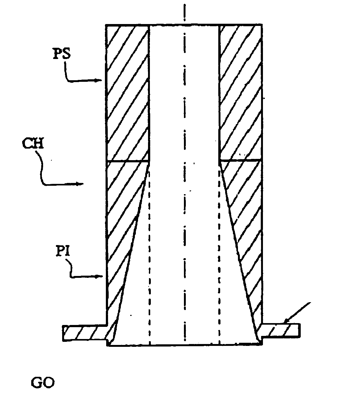
The following examples, which are in no way limitative, illustrate the merit of the invention. They are intended to demonstrate that the usual microwave and high-frequency applicators are not adapted to all products, and more particularly to weakly absorbing products. To be able to heat these products without risk of discharge, it is advisable to modify the shape of the chimney member of these applicators.
The examples also demonstrate the successive difficulties encountered in the development of the present invention.
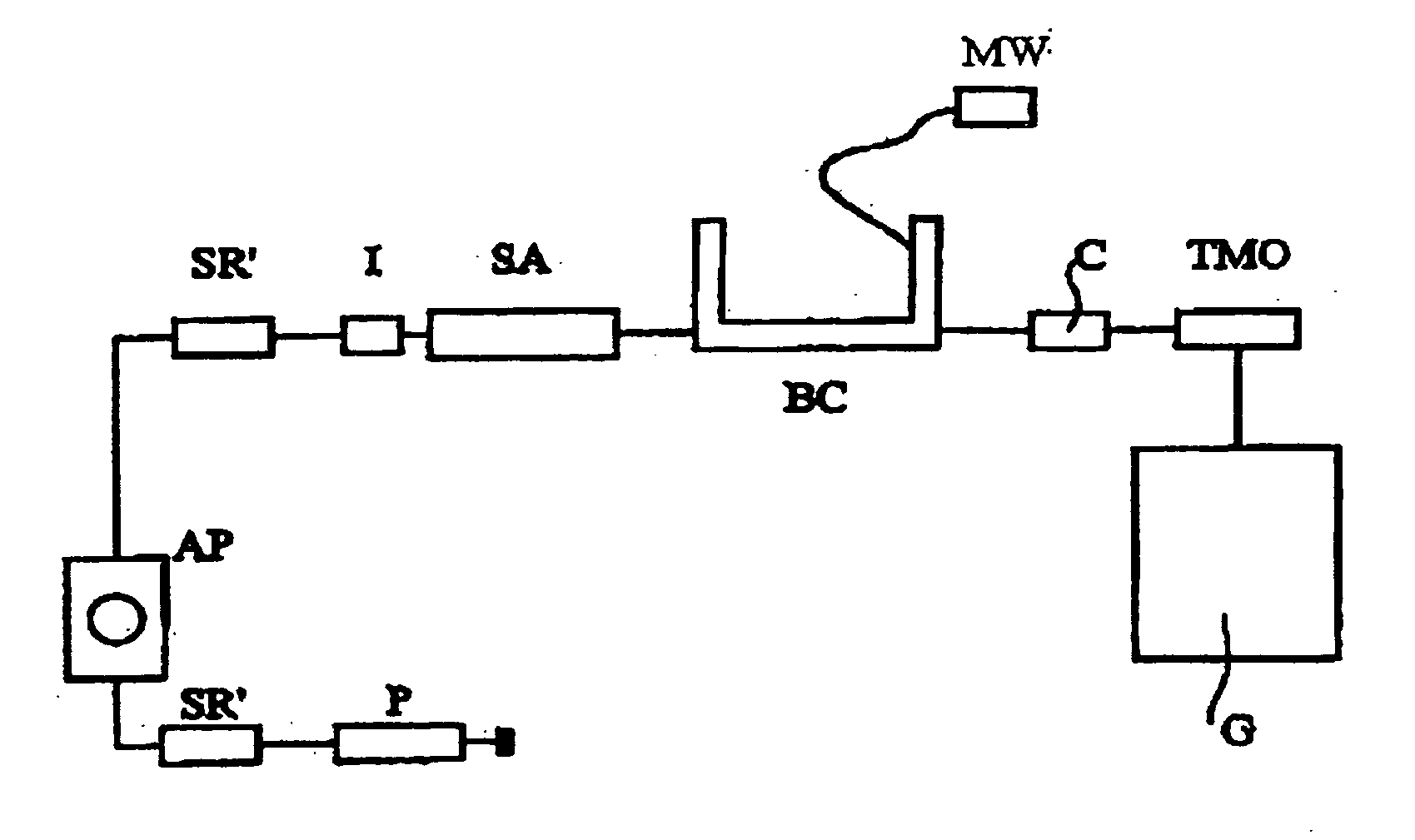
I—Appliances Used
The microwave device comprises different elements:
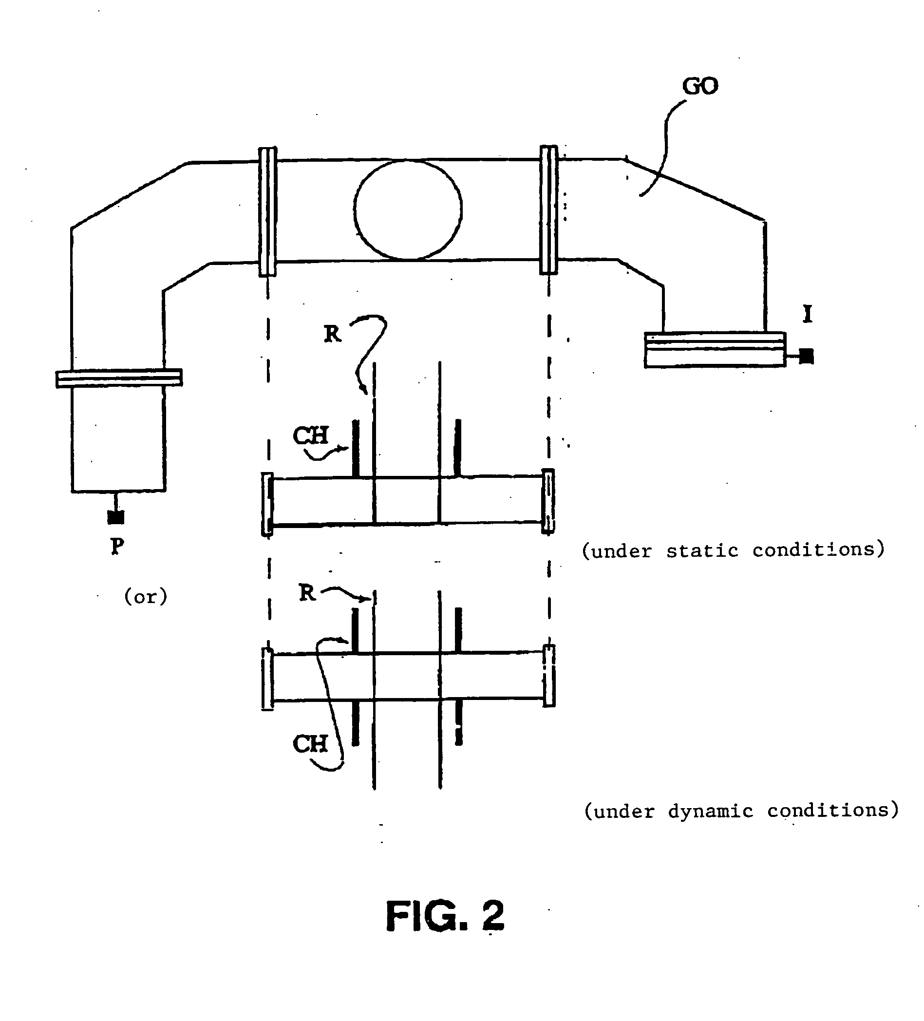
(see FIG. 1)
The microwave system is composed of a magnetron generator G operating at the frequency of 2450 MHz (λ=12 cm) at a power ranging up to 6 kW. The generator transmits the energy to the microwave head TMO, which will transform the high voltages comprising the energy to microwaves. The circulator C is a safety device, which allows the incident waves to pass and redirects the reflected waves to a water ballast, where the waves are absorbed, thus raising the water temperature. The double coupler BC makes it possible to know the reflected and incident powers by virtue of the milliwattmeter MW. The automatic stub system SA is composed of 4 insertable screws in the waveguide for the purpose of attenuating the reflected power of the system. The iris I and the short-circuit piston P make it possible to adapt the microwave system to the substance to be treated. In other words, to favor better absorption by the substance of the power emitted by the generator, the electric field must be maximal at the location of the solution, which can be achieved by appropriate adjustment of these two elements.
The system is equipped with two cooling systems SR in order to prevent any overheating. The substance is placed in the applicator AP, formed by single-mode cavities resonating at the emission frequency along a beam in the direction of the guide.
The pilot is adapted to the microwave system. It comprises the microwave reactor, positioned in the field of the waveguide. The tests can be performed under static or dynamic conditions.
II—Results:
The tests were performed by means of a 6-kW magnetron generator operating at the frequency of 2450 MHz. The single-mode applicator was constructed on the basis of a rectangular waveguide of 86 mm width and 43 mm height. In this type of applicator, the distribution of the electric field is localized and the Pyrex™ reactor is placed in maximum interaction therewith by virtue of a short-circuit piston. An impedance-matching device, placed between the generator and the applicator, also assures the adjustments necessary for optimal transfer of energy into the product to be treated.
The tests were performed under static and dynamic conditions.
Two types of chimney members CH were tested on two types of products: standard cylindrical chimney members (see FIG. 3) conical chimney members (see FIG. 4) and water: polar molecule with good dielectric characteristics rapeseed oil: molecule with poor dielectric characteristics
The values of the dielectric characteristics of these products are presented in the table below: Relative permittivity ε′ Loss factor ε″ Loss angle tan δ Water 80 20 0.25 Rapeseed oil 4.5 0.2 0.044
The experiments performed on 1.5 kg of product demonstrate the efficacy of these new chimney members: Tested Chimney member power Water Rapeseed oil Standard (cylindrical) 2 kW no arcs arcs in 10 min Conical (invention) 4 kW no arcs no arcs
III—Tests Performed
All tests were performed with rapeseed oil.
a—Test with Two Standard Chimney Members (Prior Art) of 95 and 65 mm Heights and a Microwave Reactor of 30 mm Diameter.
See FIG. 5
The test was performed on rapeseed oil with a microwave tube having an inside diameter of 30 mm and a height of 1 m. P reflected Leaks P emitted (kW) (W) (mW/cm2) Remarks 0.5 160 0 to 0.2 1 279 0.3 2 600 0.4 Arcs, glass deformed
At the moment when arcs began, the temperature was 240° C. The arcs did no break the glass, but deformed it. The strike occurred just at the beginning of the upper chimney member.
see FIG. 6
The places of the reactor that are most susceptible to arcs are those where the distance between waveguide and chimney member of the reactor is shortest. See FIG. 7
These arcs are caused by the fact that the electric field is too strong. Attempts were then made to increase the volume of product exposed to the field.
b—Chance of Configuration
The waveguide was modified in such a way as to expose a larger volume to the field.
Old Configuration
In the old configuration, the reactor traversed the waveguide at right angles to the direction of propagation of the waves.
See FIG. 8
See FIGS. 9 and 10
Total length=77.86 cm
Since λg/2=8.66
then 8 (λg/2)=69.28 and
9 (λg2)=77.94
9 half-periods are counted between the iris and the piston
New Configuration
In the new configuration, the reactor traverses the waveguide parallel to the direction of propagation of the waves.
See FIGS. 11 and 12
Total length=63 cm
7 (λg/2)=60.62
8 (λg2)=69.28
Slightly more than 7 half-periods are counted between the iris and the piston.
The reactor was filled with rapeseed oil and power tests were performed.
At 5 kW, an arc developed in 5 minutes. At 2 kW, it appeared at the end of 36 minutes. In both cases, the temperature attained did not exceed the desired temperature level.
Once again, a single arc strike occurred at the junction between the chimney member of the reactor and the waveguide:
See FIG. 13
To limit the presence of electric arcs, it must therefore be ensured that the reactor is not too close to the waveguide.
The old configuration (vertical arrangement) achieved better results. The next tests were performed with this first configuration but with new shapes of chimney members.
c—Use of Conical Chimney Members
Two criteria must be taken into account: 1—the volume exposed to the field 2—the distance between the reactor and the waveguide constituted by the chimney member
New chimney members are designed to meet these two criteria. They are characterized as conical. More precisely, they comprise a standard cylindrical portion and a conical portion at the level of the waveguide. They replace the straight cylindrical chimney members.
See FIGS. 3 and 4
The microwave reactors can then have different shapes:
See FIGS. 14 and 15
With approximately:
V1=4.33*Π*x2/4
V2=9.95*Π*32/4=70.33 cm2
V3+V4=9.95*Π*(x−3)2/4
For x=3 cm, Vtotal=171.2 cm2
For x=5 cm, Vtotal=282 cm2
For x=6 cm, Vtotal=394.3 cm2
Power tests at 4 kW were performed on reactors of 50 mm (x=5 cm) and 30 mm (x=3 cm) diameter.
With the 50-mm reactor, an arc developed at the end of 6 minutes. The reactor was too close to the waveguide.
In contrast, with the reactor having 30 mm diameter (straight reactor), no arc developed. The only arcs that can occur were observed when the reactor was weakly centered.
d—Ventilation by Humid Air
Additional tests were performed to optimize the results obtained with these new chimney members a little more.
The tests were performed with the conical chimney members and a straight reactor of 30 mm diameter (better conditions, see II-c).
To remove the static electricity, it is necessary to promote good ventilation by humid air or by another gas having comparable values of dielectric constants (example: SF6 at 1 bar). In the present case, water vapor was injected at the applicator. To prevent water from condensing on the reactor walls, it was necessary to add suction at the outlet of the chimney members.
With gentle suction, an arc developed at 282° C. and Pi=5 kW.
With very strong suction, an arc developed at 284° C. and Pi=6 kW. At 5 kW, however, no arc developed.
Ventilating with humid air therefore improves the results. Nevertheless, the ventilation must be sufficiently intensive to achieve a real effect.
Conclusions of the Tests:
The tests performed at 2450 MHz show that the system of chimney members in “conical” shape then makes it possible to avoid electric arcs at high emitted power (4 kW, instead of 2 kW with the standard chimney members). During operation at such powers, the desired temperature level (up to 400° C.) is reached very rapidly, or in other words in less than 15 minutes for the treatment of 1 kg of product.
It will be entirely preferable, without being limitative, to use the dimensions and shapes illustrated in FIG. 4, which represents the best embodiment of the invention to date. As is evident, a chimney member having a conical lower portion and a cylindrical upper portion is used in this case.
The invention also covers all the embodiments and all the applications that will be directly accessible to the person skilled in the art from reading this application, from his own knowledge and possibly from simple routine tests.

PUM

no PUM

Description & Claims & Application Information

We can also present the details of the Description, Claims and Application information to help users get a comprehensive understanding of the technical details of the patent, such as background art, summary of invention, brief description of drawings, description of embodiments, and other original content. On the other hand, users can also determine the specific scope of protection of the technology through the list of claims; as well as understand the changes in the life cycle of the technology with the presentation of the patent timeline. Login to view more.
Why Eureka
Try Eureka