
Nasal cannula assembly

a cannula and nasal tube technology, applied in the field of cannula assembly, can solve the problems of pain for patients, deep and irritating impression, and pain of patients, and achieve the effects of small size, stable position, and barely felt by wearers

Active Publication Date: 2005-02-10
THOMPSON PAUL S
View PDF2 Cites 268 Cited by
  • Summary
  • Abstract
  • Description
  • Claims
  • Application Information

AI Technical Summary

Benefits of technology

[0019] A nasal cannula assembly with a nasal cannula that is lightweight, small in size, stable in position with nares that positively guide the gas flow along the natural contours of the nasal passages and are barely felt by the wearer. Extremely flexible support tubing that reliably orients and positions the cannula with little or no tension on the face and flexible main supply tubing that is very manageable, remains flexible at low temperature and has little tendency to form twisted loops that block flow.
[0020] The nasal cannula assembly just described is a combination of three inventions, (i) cannula (ii) support tubing (iii) main supply tubing, that provide a new product that markedly improves comfort to the wearer. Each invention can be used independently or in various combinations to improve comfort and utility of prior art nasal cannula assemblies.
[0021] The first invention is a vee-shaped cannula, or nosepiece that conforms to the natural contours of the face and improves the fit and comfort and has nares with extremely flexible tips that curve inward to prevent either the tips or the gas flow from hitting the walls. The flexible rim at the tips will yield to nose hairs instead of disturbing them thus eliminating sensation. This cannula offers a significant improvement in comfort when used with prior art support tubing.
[0022] The second invention is support tubing with specific properties that work in concert with the shape of the cannula to reduce tubing tension to a bare minimum yet secure the placement of the cannula. It is made from an ultra-high molecular weight PVC resin that gives it rubber-like qualities such as resilience, extreme flexibility and low compression set yet bonds with solvent like regular PVC and remains flexible at low temperatures. This support tubing can be used with all cannulas that do not rely on torsional stiffness from the support tubing to maintain the rotational orientation of the cannula body. The low force required to coil the tubing for packaging allows the cannula to be thinner and lighter without kinking in the package.
[0023] The third invention is main supply tubing made from the same or similar material as the support tubing. The flexibility and resilience allow it to lay flat like wet spaghetti so that it is very manageable and is highly resistant to forming the twisted loops common with prior art tubing. The material has very good low temperature flexibility and improves the utility of the cannula when outside in a cold environment. This material can be used for the main supply tubing of any type of cannula or support tubing.

Problems solved by technology

The problems with the prior art arrangement are many and significant.
Thus, in order to have the cannula smartly fitted into the patient's nostrils, as desired, the oxygen supply lines are typically wrapped quite tightly about the patient's ears and this is very painful for the patient.
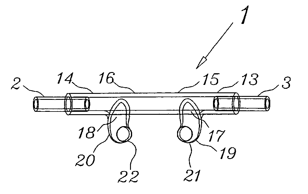
Additionally, the tubing across the face leaves an unsightly, deep and irritating impression that becomes semi-permanent so long as the oxygen therapy continues.
These impressions in the face of the patient are cosmetically undesirable and, in some cases, the pressure exerted by the tubes against the upper cheeks tends to force the patient's eyes closed, thus interfering with clear vision and causing watering of the eyes.
Another serious problem associated with the typical cannula oxygen supply system described above and with other previous designs is that the weight of the cannula results in a tendency to fall out of the patient's nostrils.
For some patients this is simply unacceptable.
Accordingly, continued contact of the cannula, especially at the philtrum and around the unprotected upper lip and cheek areas causes inflammation and irritation and ulcerous conditions may occur after a period of time.
Not only does the wearer inadvertently move the cannula while sleeping as the head moves from side to side, but also when eating and / or talking, further movement occurs.
The cannula can easily tilt to the side allowing the hollow tubular nasal extensions, or nares, to come out of the nostril, contact the nasal walls or direct gas against the wall, all of which are a common source of discomfort.
The tips of the nares deflect hairs inside the nostrils causing an unpleasant sensation that is especially disconcerting to a patient not accustomed to wearing these devices.
Gravity acts to make the cannula fall out but it can also cause it to roll out of the nostrils on cannulas with a high center of gravity.
Insufficient flexibility and “memory” of the PVC tubing cause forces acting on one end of the tubing to affect the cannula at the other end.
Insufficient flexibility, or stiffness, increases the force needed to bend the tubing when the head or parts of the face are moved and the cannula reacts to these forces by lifting off the face or tilting to the side.
The various rubbing actions that occur with each movement cause red spots and irritation under the nose and on the ears.
Unfortunately the correct angle for comfort is a fairly narrow range and the predetermined angle is set by hand so a significant number of cannulas do not fit well.
An integral tab in the cannula body is designed to rest against the lip to rotate the cannula back into position by twisting the tubing and this can be a source of irritation.
Although undesirable tension is required to bend the cannula body, this style of prior art cannula does not require torsional rigidity to orient the nares and, in fact, the torsional rigidity can actually interfere with proper pointing in cases where the tubing is bonded such that it tries to rotate the cannula at some other angle.
The main supply tubing is generally made from the same material as the support tubing and also causes a number of problems in prior art cannulas.
Regular PVC used in prior art cannulas have poor low temperature flexibility and become very stiff outside in the winter and have even been known to snap in two.
It also has poor compression set properties that give it memory.
Due to the stiffness of the material, movements that should only affect a small section of tubing, instead, involve longer sections that increase the likelihood of catching or entangling on some object.
This same characteristic also causes the main supply tubing to form twisted loops that kink and block the flow of oxygen, particularly in longer lengths.
These humps increase the chance of the tubing becoming caught under foot or entangled and they are also the reason that it is so common for prior art tubing to form twisted loops that eventually cut off the oxygen supply.
Various swivel connectors have been developed to prevent this problem but they cause problems themselves by becoming caught in doorjambs or on furniture legs as they are dragged along.
Further, there is a need for a cannula to fit properly when first removed from the package and reduce the storage space needed to maintain a cannula inventory.

Method used


Image

  • Nasal cannula assembly
  • Nasal cannula assembly
  • Nasal cannula assembly

Examples


Embodiment Construction

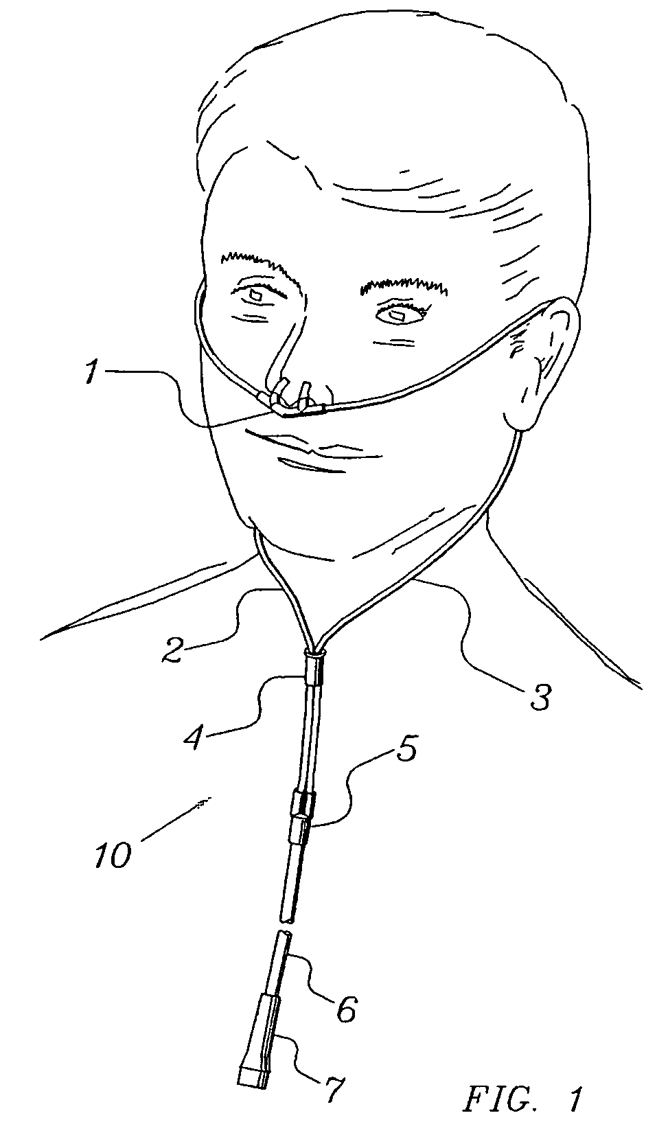
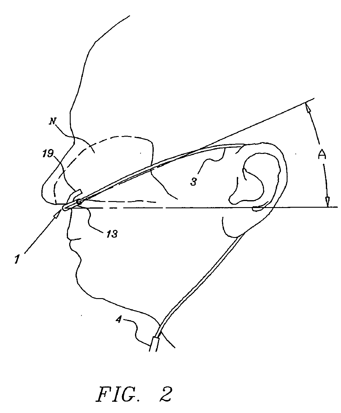
[0038] The novel nasal cannula assembly will now be described by referring to the drawings. In FIG. 1, the cannula assembly, generally designated numeral 10 is illustrated in position on a patient's face. The assembly comprises nasal cannula 1, a pair of support tubes 2 and 3 connected to opposite ends of the cannula, main oxygen supply line 6, fork connector 5 for joining support tubes 2 and 3 to main supply tube 6 and a slip loop 4 disposed about support tubes 2 and 3. The structure of cannula 1 is best understood by viewing FIGS. 3-5. The composition of the cannula is preferably of a thermoplastic composition such as polyvinyl chloride or polyvinyl acetate that are quite pliable or flexible and is normally fabricated using a dip molding process, although the shape of the cannula is suitable for injection molding. The plasticizer used to add flexibility is preferably one that resists migration from the cannula to the skin.

[0039] The cannula is generally a hollow tubular member ha...


PUM


Abstract

A nasal cannula assembly designed for contact with the nasalabidial area of a patient's face comprising a nasal cannula, a pair of oxygen supply tubes connected to opposite ends of the nasal cannula and a main oxygen supply line. The nasal cannula is made of a flexible plastic material molded into a light-weight hollow tubular member having a main body portion formed at an acute angle in the center and having a pair of spaced exterior orifices projecting from the body at an angle and curved upwardly and inwardly for directing gas flow into a patient's nostrils. Attachment points for oxygen supply tubes are above center of gravity of the nasal cannula to make it self-righting thus eliminating need for stiff supply tubing to orient cannula. Oxygen supply tubes made from ultra-high molecular weight PVC possess superior flexibility and low compression set so that little tension on the tubing is required to hold cannula in proper position. A main oxygen supply line made from ultra-high molecular weight PVC resists the formation of twisted loops that tend to block oxygen flow.

Description

BACKGROUND OF INVENTION [0001] Oftentimes a patient will require a continuous oxygen supply while at a medical facility or while at home under medical care. Oxygen delivery devices, such as the cannula, are well known in the medical arts. The typical means and method for attaching an oxygen supply cannula to a patient's nostrils involves attaching a pair of oxygen supply lines to the cannula and inserting the appropriate portions of the cannula into the patient's nostrils. Next, the oxygen supply lines are wrapped around the patient's ears and the remaining portions of the oxygen supply lines are left to hang below the patient's chin, where an adapter couples the two oxygen supply lines into a single oxygen supply line. Additionally, below the chin of the patient, most systems use a slide connector to hold the two supply lines snugly against the patient's neck. [0002] The problems with the prior art arrangement are many and significant. First, the reason that the oxygen supply lines...

Claims


Application Information

Patent Timeline
Patent Type & Authority Applications(United States)
IPC IPC(8): A61M25/02
CPCA61M16/0666A61M2025/0226A61M25/02
Inventor THOMPSON, PAUL S.
Owner THOMPSON PAUL S
Learn More