
Methods for electrically isolating a portion of the atria

a technology of electrical isolation and atria, which is applied in the field of atrial appendages, can solve the problems of enlargement of one or both atria to up to 2-3 times the normal size, inefficient blood transport in certain regions of the atria, and continued blood stasis in certain regions, so as to reduce the size of the region

Inactive Publication Date: 2005-02-10
EP TECH
View PDF57 Cites 89 Cited by
  • Summary
  • Abstract
  • Description
  • Claims
  • Application Information

AI Technical Summary

Benefits of technology

[0007] An important aspect of the invention involves providing methods and devices to reposition the atrial appendages, for example by inversion thereof either totally or partially. In accordance with this aspect of the invention, several embodiments of devices are provided for grabbing or otherwise attaching themselves to an appendage wall and either inverting or otherwise pulling the walls of the appendage together to reduce the size of the region of potential blood stasis, and consequently the volume of the affected atrium. In accordance with this aspect, it is an object of the invention to reduce the region of potentially static blood and, hence the thrombogenicity of the atrium.
[0008] In accordance with one embodiment addressing this aspect of the invention, a device is provided which uses a distal helical coil to penetrate the appendage wall and, thus, provide an attachment for pulling the appendage inwardly into the atrium. In accordance with a further, alternative, embodiment, a multi-pronged grabbing device is provided on the distal end of a catheter which enables grabbing of the appendage surface with the prongs for pulling on the walls to cause an inversion thereof and / or to reduce atrial volume. In accordance with a still further alternative embodiment, a device is provided which perforates the appendage wall and then this, or another member is inserted to expand on the exterior appendage wall surface, thereby anchoring the catheter to the appendage wall so that the wall may be pulled into the atrium.

Problems solved by technology

Atrial fibrillation and abnormalities which may lead to atrial fibrillation (such as mitral and / or tricuspid regurgitation) are often associated with abnormal electrical propagation through the heart leading to inefficient transport of blood in certain regions of the atria, and / or an enlargement of one or both atria to up to 2-3 times the normal size.
However, such minimally invasive procedures may result in regions of continued blood stasis, particularly in the atrial appendages due to electrical isolation of the appendages or decreased contractility of the tissue due to the destruction of large regions of atrial tissue.
Also, the response of the atria to permanent conversion from atrial fibrillation to sinus rhythm after a catheter-based and / or surgical maze procedure has not been proven to return appendage function to normal.

Method used


Image

  • Methods for electrically isolating a portion of the atria
  • Methods for electrically isolating a portion of the atria
  • Methods for electrically isolating a portion of the atria

Examples


Embodiment Construction

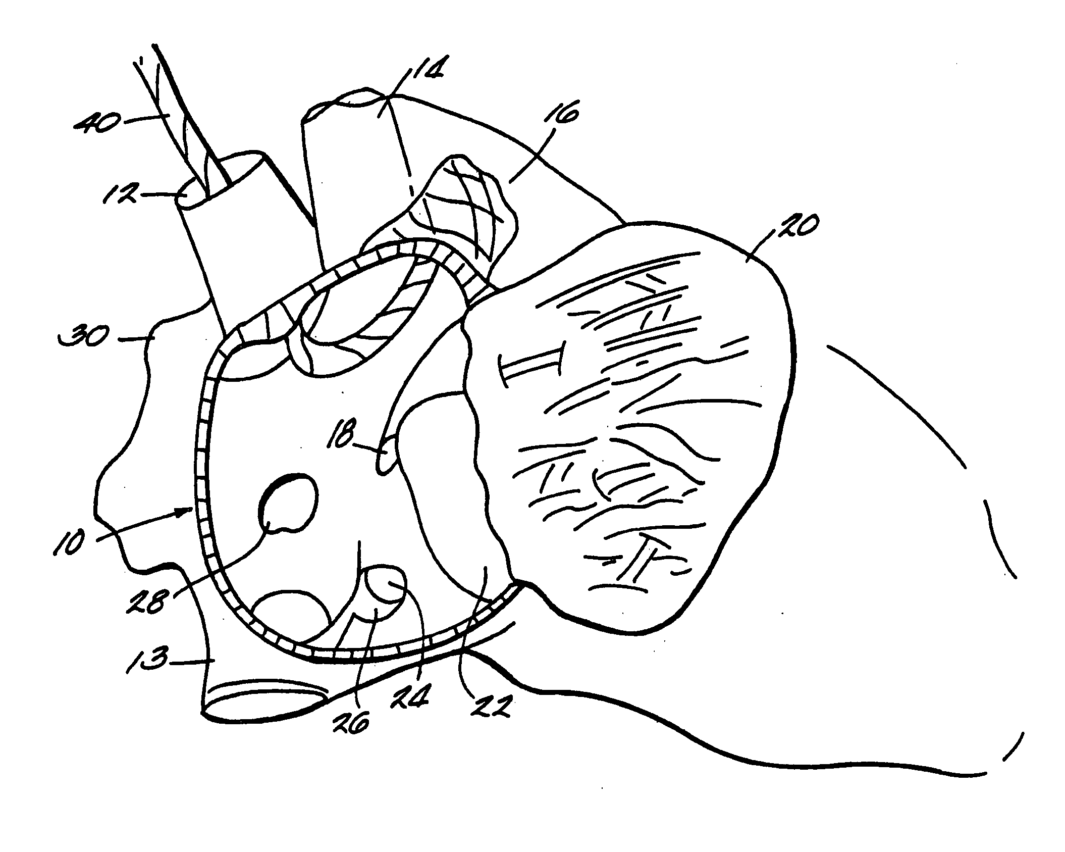
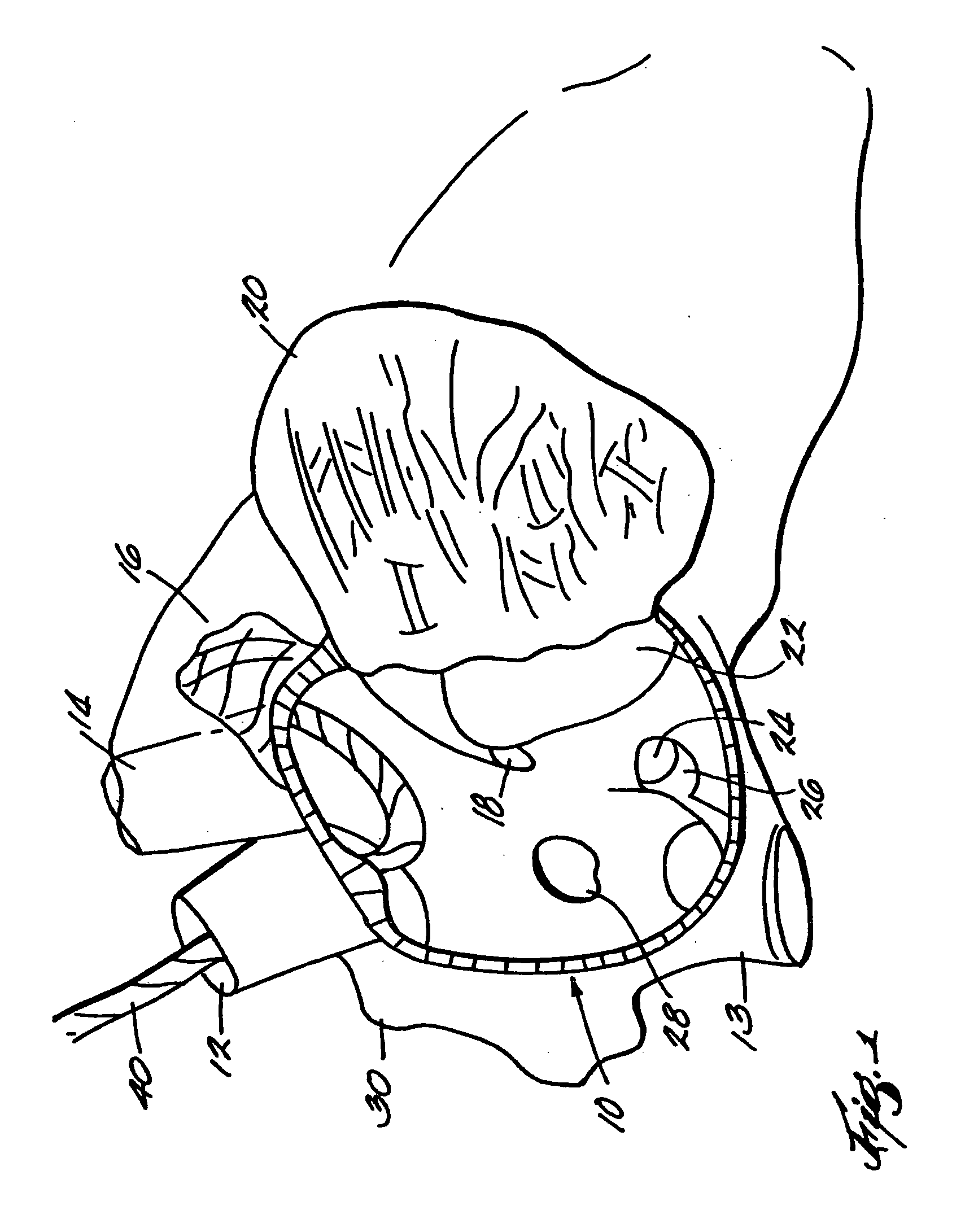
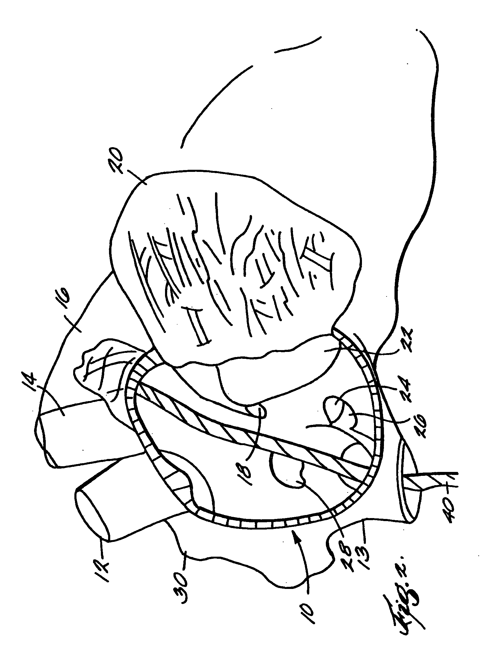
[0059] Referring more specifically to the drawings, FIGS. 1-3 show, in fragmentary fashion, the right atrium 10, the superior vena cava 12, the inferior vena cava 13, the ascending aorta 14, the right atrial appendage 16, the membranous septum 18, the right atrial freewall 20, the tricuspid valve 22, the opening of the coronary sinus 24, the valve of the coronary sinus 26, and the fossa ovalis 28.

[0060] A left atrium 11 is shown in FIGS. 4-6. There are also seen therein the aortic valve 15, the left atrial appendage 17, the left superior pulmonary vein 19, the mitral valve 21, and the left ventricle 32.

[0061] A catheter 40 is shown generally being introduced into the atria of a heart through various cardiovascular introduction passageways as will be discussed hereinafter. The point of attachment of catheter 40 to the wall of an atrial appendage 16 or 17 is indicated generally at 42.

[0062] Referring to FIGS. 1-6, various ways of entering a heart chamber and positioning a catheter ...


PUM


Abstract

Devices for insertion into an atrial appendage of stasis reducing components such as mesh members, chemical bonding agents or expandable anchors are disclosed.

Description

FIELD OF THE INVENTION [0001] This invention relates to the reduction of regions of blood stasis and ultimately thrombus formation in such regions, particularly in the atrial appendages for patients with atrial fibrillation. More specifically, the invention relates to procedures and devices for affixing the atrial appendages in an orientation that reduces subsequent formation of thrombus. BACKGROUND OF THE INVENTION [0002] The atria must enable organized electrical propagation from the SA Node to the AV Node to stimulate the atria to contract in an organized way to transport blood from the atria to the ventricles, and to provide timed stimulation of the ventricles. The atrial appendages are especially important in the transport of blood because they have a sack-like geometry with a neck potentially more narrow than the pouch. In this case, contraction of the appendage is essential to maintain an average absolute blood velocity high enough to eliminate potential stasis regions which ...

Claims


Application Information

Patent Timeline
Patent Type & Authority Applications(United States)
IPC IPC(8): A61B17/00A61B18/12A61B17/02A61B17/064A61B17/12A61B17/30A61B17/34A61M29/00
CPCA61B17/00234A61B17/0218A61B17/0469A61B17/064A61B17/12013A61B2017/3488A61B2017/00349A61B2017/0443A61B2017/0464A61B2017/048A61B2017/0649A61B2017/00243
Inventor FLEISCHMAN, SIDNEY D.WHAYNE, JAMES G.BOURNE, THOMAS M.SWANSON, DAVID K.
Owner EP TECH
Learn More