Electrically conductive glass and photoelectric conversion element using the same

a technology of photoelectric conversion element and conductive glass, which is applied in the direction of conductive layers on insulating supports, electrochemical generators, electrolytic capacitors, etc., can solve the problems of leakage current flow, disadvantage in cost, and flow of leakage curren

Inactive Publication Date: 2005-02-17
THE FUJIKURA CABLE WORKS LTD
View PDF3 Cites 52 Cited by
  • Summary
  • Abstract
  • Description
  • Claims
  • Application Information

AI Technical Summary

Problems solved by technology

However, in a dye-sensitized solar cell assembled using this electrically conductive glass, there may be backflow of electrons from the grid 13 to the electrolyte between grid 13 and the electrolyte resulting in the flow of leakage current.
However, in the case of a barrier layer obtained by this type of thin film formation method, there is the risk of the formation of slight pinholes, and even a single pinhole can result in the flow of leakage current.
Although the barrier layer should only be formed on the grid 13 in order to resolve this problem, the problem of the pinholes remains, and their formation requires a bothersome process such as photolithography, thereby making this disadvantageous in terms of cost.
However, in the case of providing a grid 13 made of nickel directly on a transparent electrically conductive film 12 comprised of FTO and so forth, the nickel serving as the grid 13 penetrates into the transparent electrically conductive film 12 resulting in deterioration of the transparent electrically conductive film 12 during standing for a long period of time or when subjected to a heat treatment.
Consequently, there was also a problem of electrons flowing back into the electrolyte from the transparent electrically conductive film 12, the leakage current flowing between the transparent electrically conductive film 12 and the electrolyte, thereby a significant decrease in the photoelectric conversion efficiency occuring when used in a dye-sensitized solar cell.

Method used


Image

  • Electrically conductive glass and photoelectric conversion element using the same
  • Electrically conductive glass and photoelectric conversion element using the same
  • Electrically conductive glass and photoelectric conversion element using the same

Examples


example 1

[0098] This Example 1 corresponds to the previously described first embodiment.

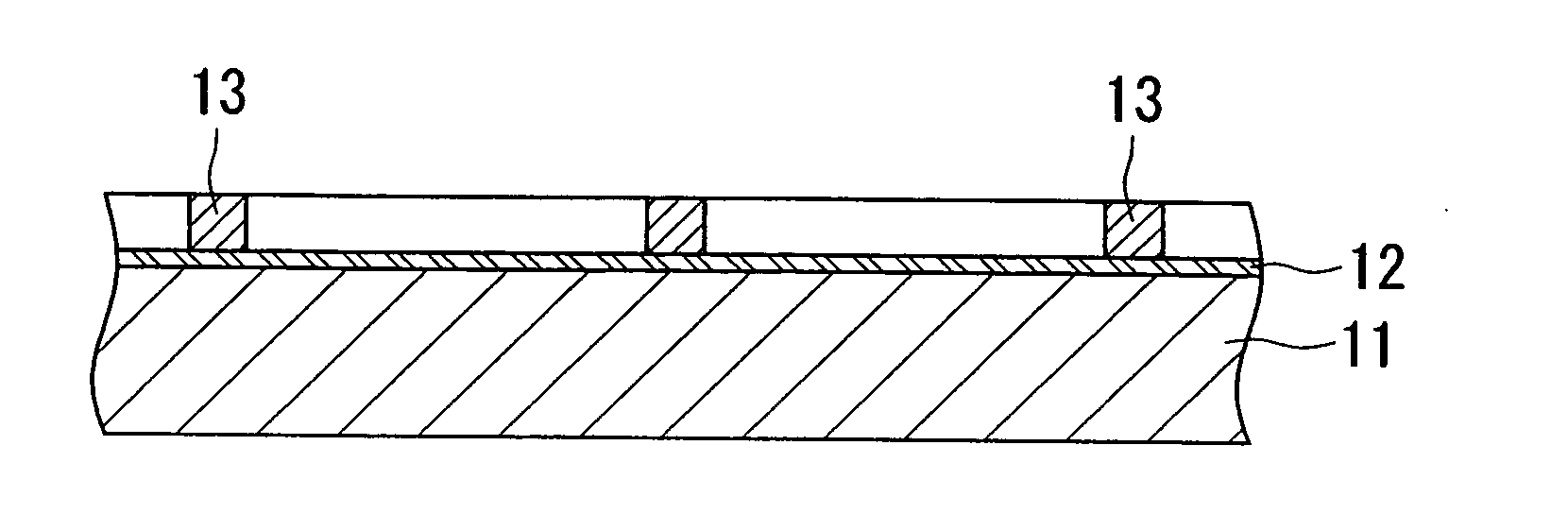
[0099] A transparent electrically conductive glass was prepared in which a transparent electrically conductive film composed of FTO having a thickness of 0.5 μm was provided on a glass plate having a thickness of 2 mm.

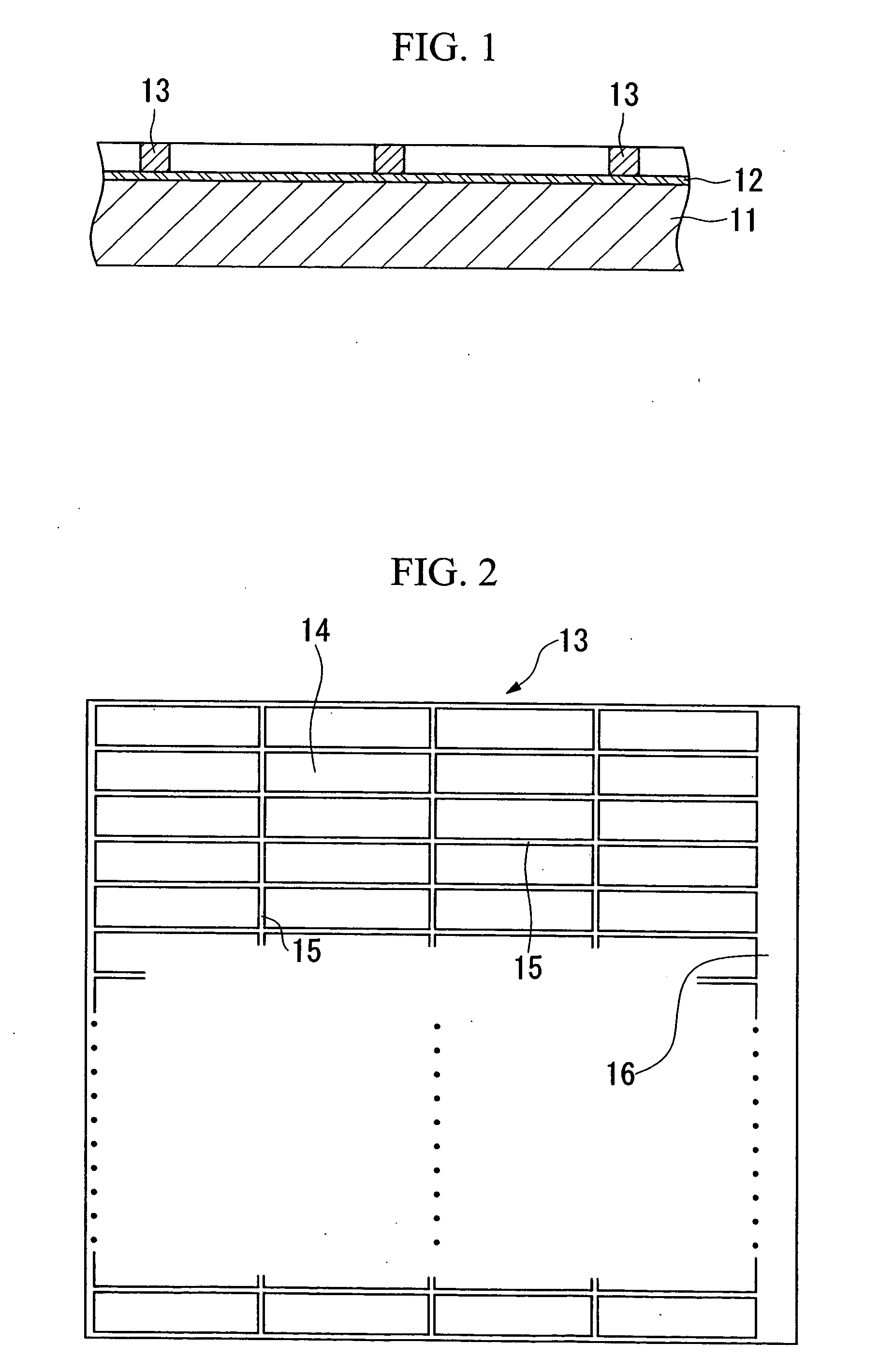
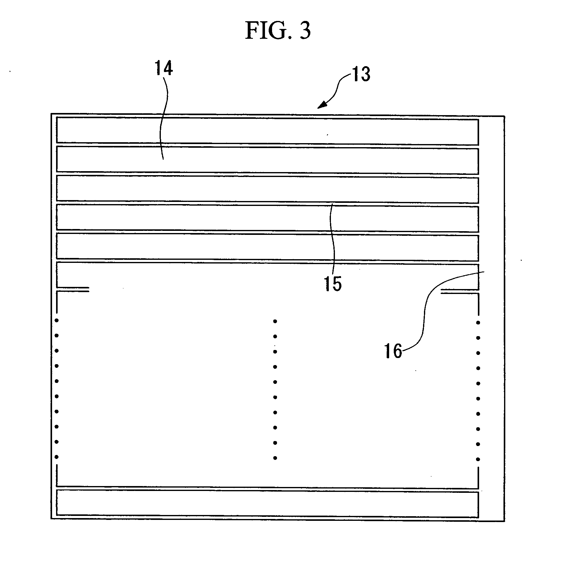
[0100] A lattice-shaped grid like that shown in FIG. 2 was provided on the aforementioned FTO of this transparent electrically conductive glass. The types of metal that served as the grid along with their formation methods were as indicated below, however, a barrier layer composed of titanium oxide or FTO was formed for some of the metals for the sake of comparison.

FormationNo.MetalMethod 1AluminumVapordeposition 2TitaniumSputtering 3ChromiumPlating 4CobaltPlating 5NickelPlating 6GoldPlating 7PlatinumPlating 8SilverPlating 9PlatinumPlatingFormation of barrier layer composed oftitanium oxide10GoldPlatingFormation of barrier layer composed oftitanium oxide11SilverPlatingFormation of barrie...

example 3

[0126] Example 3 corresponds to the aforementioned second embodiment.

[0127] A commercially available electrically conductive glass (Asahi Glass Co., LTD.) was prepared in which a transparent electrically conductive film having a thickness of 0.5 μm and composed of FTO was provided on a glass plate having a thickness of 2 mm.

[0128] A seed layer having a thickness of 0.05 μm and composed of nickel was formed on the FTO of this transparent electrically conductive film by sputtering.

[0129] Next, a diffusion-preventing film having a thickness of 0.025 μm and composed of titanium or chromium was formed on this seed layer by sputtering.

[0130] Next, after plating nickel onto this diffusion-preventing film using a nickel sulfamate solution in the same manner as the previously described production process, a heat treatment was carried out at 450° C. to provide a lattice-shaped grid composed of nickel as shown in FIG. 2 and an electrically conductive glass was produced. At this time, the d...


PUM

PropertyMeasurementUnit
thicknessaaaaaaaaaa
thicknessaaaaaaaaaa
thicknessaaaaaaaaaa

Abstract

The electrically conductive glass is obtained by providing a transparent electrically conductive film 12 such as ITO or FTO on a glass plate, and providing a grid including a film of a passivated metal on this transparent electrically conductive film. An insulating, fine oxide film formed on the surface of the passivated metal prevents leakage current from flowing from the grid to an electrolyte. In addition, leakage current is prevented from flowing from the transparent electrically conductive film to the electrolyte by providing a diffusion-preventing film including titanium or titanium oxide between the transparent electrically conductive film and the grid.

Description

TECHNICAL FIELD [0001] The present invention relates to a electrically conductive glass used in a dye-sensitized solar cell or other photoelectric conversion element, having high electrical conductivity and transparency, which is able to reduce leakage current when used in a photoelectric conversion element. [0002] The present application claims priority on Japanese Applications 2002-86859 filed on Mar. 26, 2002 and 2002-333598 filed on Nov. 18, 2002, the contents of which are incorporated herein by reference. BACKGROUND ART [0003] An invention of a prior application was previously filed by the inventor of the present invention relating to this type of electrically conductive glass in the form of Japanese Patent Application No. 2001-400593 (filing date: Dec. 28, 2001). [0004]FIGS. 1-3 show an electrically conductive glass. [0005] In FIG. 1, reference symbol 11 indicates a glass plate. This glass plate 11 is made of soda glass, heat-resistant glass, or quartz glass and so forth havin...

Claims


Application Information

Patent Timeline
Patent Type & Authority Applications(United States)
IPC IPC(8): H01G9/20H01B5/14H01L31/0224H01L31/04H01M14/00
CPCB32B17/06H01G9/2031H01G9/2068Y02E10/542H01L51/445H01M14/005H01L31/022466H10K30/83H01B5/14H01L31/04H01M14/00
Inventor OKADA, KENICHIMATSUI, HIROSHITANABE, NOBUO
Owner THE FUJIKURA CABLE WORKS LTD
Why Eureka
Try Eureka