
Program product and data processing system

a technology of program products and data processing systems, applied in the field of control, can solve the problems of increasing hardware costs, and achieve the effects of short time, reduced or shorter time, and more flexible reconfiguration

Inactive Publication Date: 2005-02-17
IP FLEX INC
View PDF20 Cites 19 Cited by
  • Summary
  • Abstract
  • Description
  • Claims
  • Application Information

AI Technical Summary

Benefits of technology

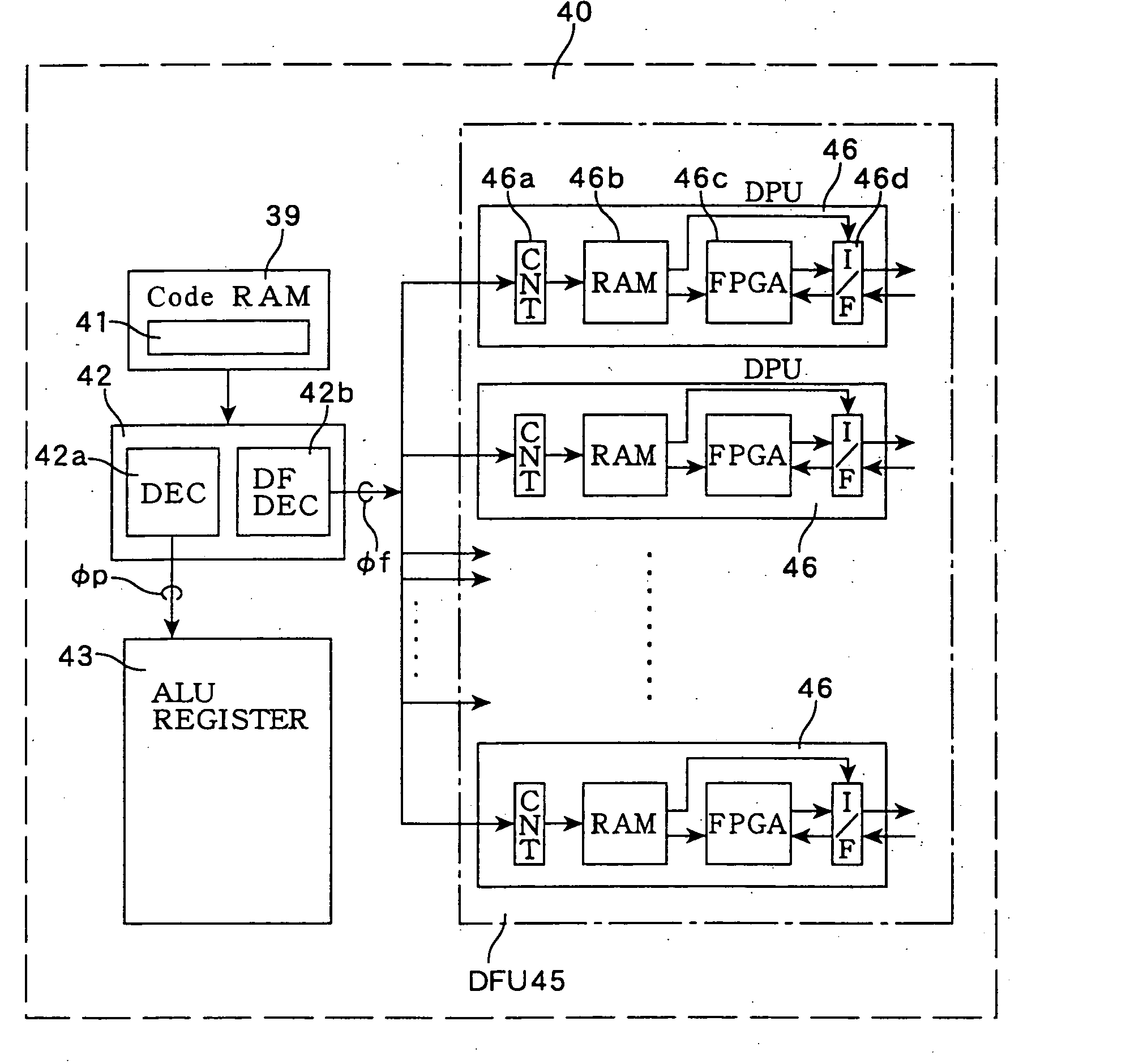
[0011] Conventionally, the only way to handle with a complicated data processing is to prepare dedicated circuitry and implement a special instruction for using the circuitry, thereby increasing the hardware costs. In contrast, in the system of the present invention, such as the program product, data processing system and control method thereof, the interfaces of the processing unit as an arithmetic / logic unit are described, making it possible to introduce the structure of pipeline control and data path control into an instruction set, i.e., program product. This allows various data processings to be described with the program and executed with suitable hardware, whereby the data processing system having both the software flexibility and high-speed performance using dedicated circuitry is provided by this invention. Moreover, these data paths can be implemented without discontinuing execution of a main processing or general-purpose processing, therefore, the hardware is dynamic reconfigured during execution of an application.
[0020] It is also desirable that the data flow designation unit has a function as a scheduler for managing the interface of the processing unit, in order to manage a schedule retaining the interface of each processing unit that is set based on the data flow designation instruction. For example, in the case where matrix calculation is performed only for a fixed time and filtering is conducted thereafter, the connection between the processing units within the data processing system are performed prior to execution of each processings and the each connection is kept using a time counter. Replacing the time counter with another comparison circuit or external event detector enables more complicated, flexible scheduling to be implemented.

Problems solved by technology

Conventionally, the only way to handle with a complicated data processing is to prepare dedicated circuitry and implement a special instruction for using the circuitry, thereby increasing the hardware costs.

Method used


Image

  • Program product and data processing system
  • Program product and data processing system
  • Program product and data processing system

Examples


Embodiment Construction

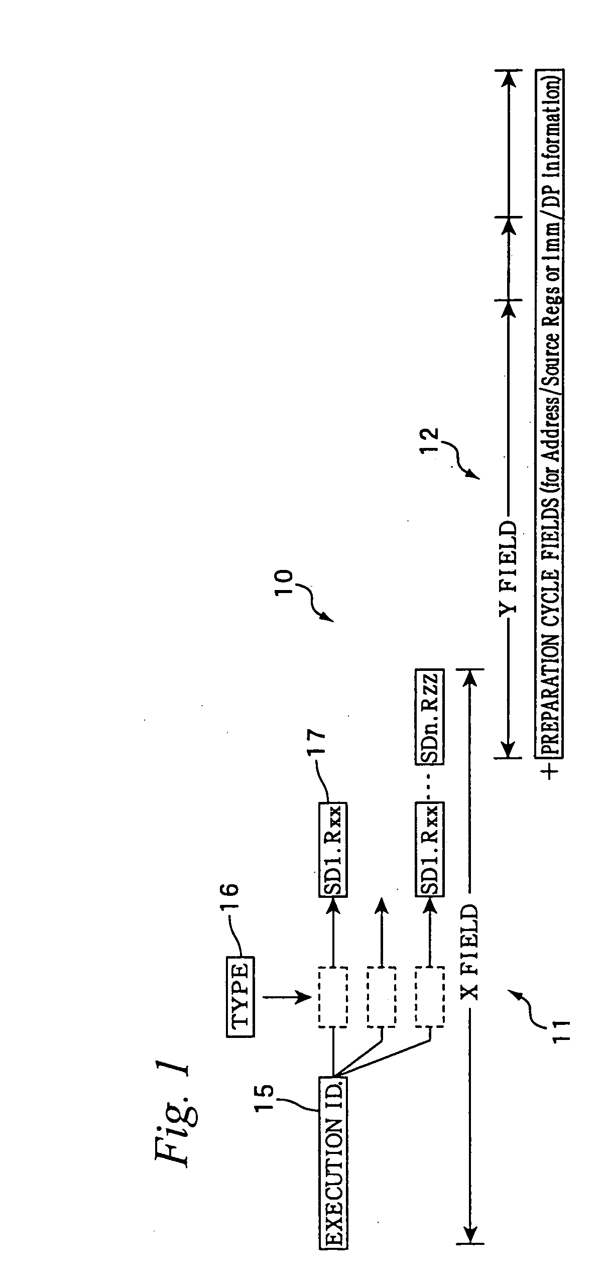
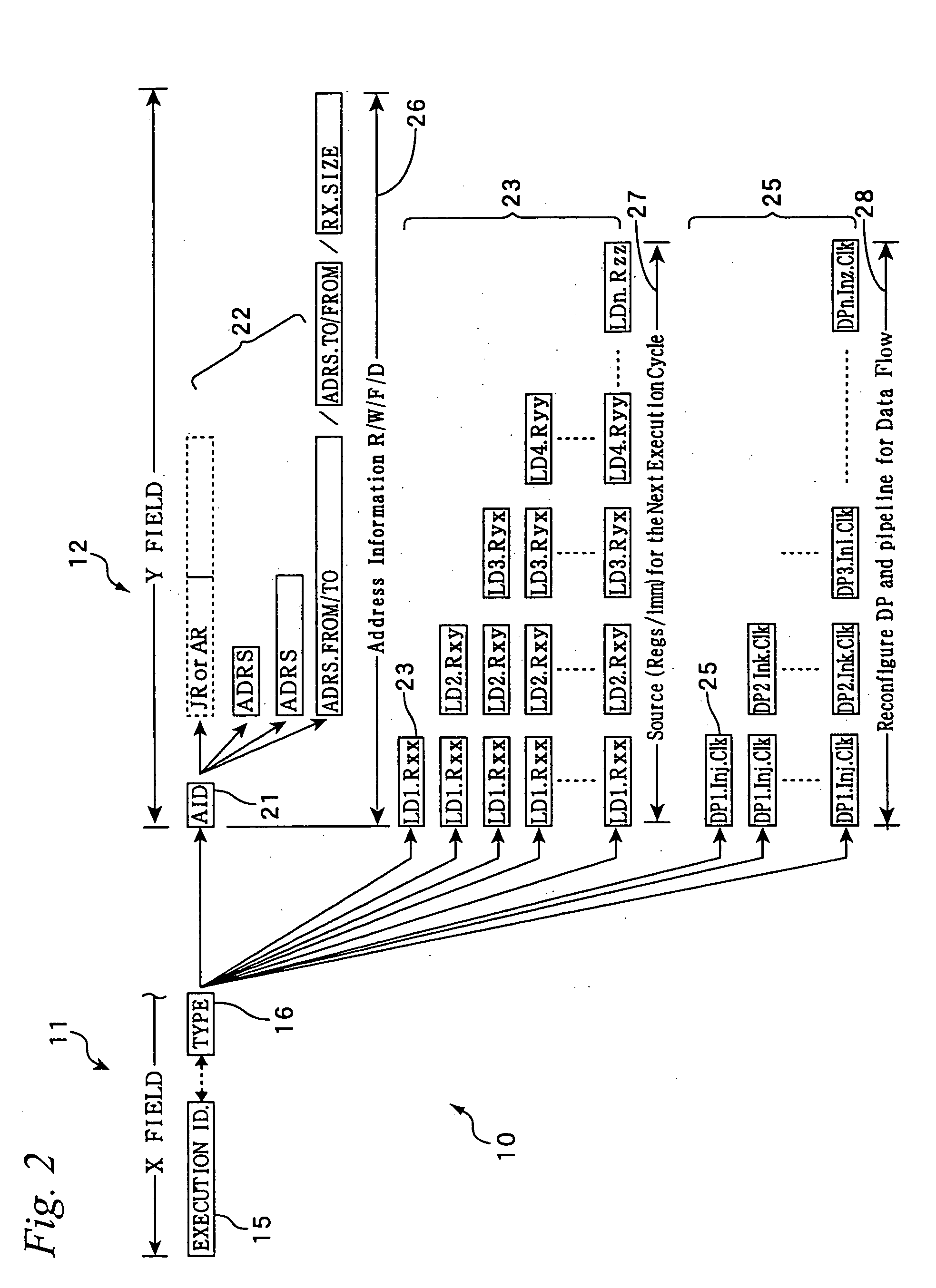
[0038] Hereinafter, the present invention will be described in more detail with reference to the drawings. FIG. 1 shows the structure or format of the instruction set (instruction format) according to the present invention. The instruction set (instruction set of DAP / DNA) 10 in the present invention includes two fields: a first field called instruction execution basic field (X field) 11 and a second field called instruction execution preparation cycle field (additional field or Y field) 12 capable of improving efficiency of the subsequent instruction execution. The instruction execution basic field (X field) 11 specifies a data operation such as addition / subtraction, OR operation, AND operation and comparison, as well as the contents of various other data processings such as branching, and designates a location (destination) where the operation result is to be stored. Moreover, in order to improve the utilization efficiency of the instruction length, the X field 11 includes only inf...


PUM


Abstract

In the present invention, an input and / or output interface of at least one of a plurality of processing units forming a data processing system is designated independently of timing of execution of the processing unit, so as to allow the plurality of processing units to define various data paths at the program level. The present invention makes it possible to flexibly execute individual complicated data processes with hardware at a high speed without having various dedicated circuits fixed specifically to the respective data processings.

Description

TECHNICAL FIELD [0001] The present invention relates to a control program product described with microcodes or the like, and a data processing system capable of executing the control program. BACKGROUND OF INVENTION [0002] Processors (data processing systems or LSIs) incorporating an operation function such as microprocessor (MPU) and digital signal processor (DSP) are known as apparatuses for conducting general-purpose processing and special digital data processing. Architectural factors that have significantly contributed to improved performance of these processors include pipelining technology, super-pipelining technology, super-scalar technology, VLIW technology, and addition of specialized data paths (special purpose instructions). The architectural elements further include branch prediction, register bank, cache technology, and the like. [0003] In the VLIW technology, the data paths are configured in advance so as to allow for parallel execution, optimization is conducted so t...

Claims


Application Information

Patent Timeline
IPC IPC(8): G06F9/30G06F9/318G06F9/38
CPCG06F9/30076G06F9/30145G06F9/3016G06F9/3897G06F9/30181G06F9/3885G06F9/30167G06F9/30
Inventor SATO, TOMOYOSHI
Owner IP FLEX INC
Learn More