Light-emitting device and manufacturing method thereof
a technology of light-emitting devices and manufacturing methods, which is applied in the direction of semiconductor devices, electrical devices, basic electric elements, etc., can solve the problems of low light emission efficiency, and ultra-violet light-emitting devices, and achieve high-efficiency light emission.
- Summary
- Abstract
- Description
- Claims
- Application Information
AI Technical Summary
Benefits of technology
Problems solved by technology
Method used
Image
Examples
first embodiment
[0027] (First Embodiment)
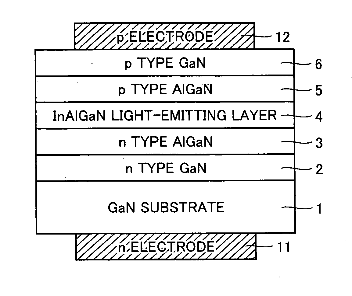
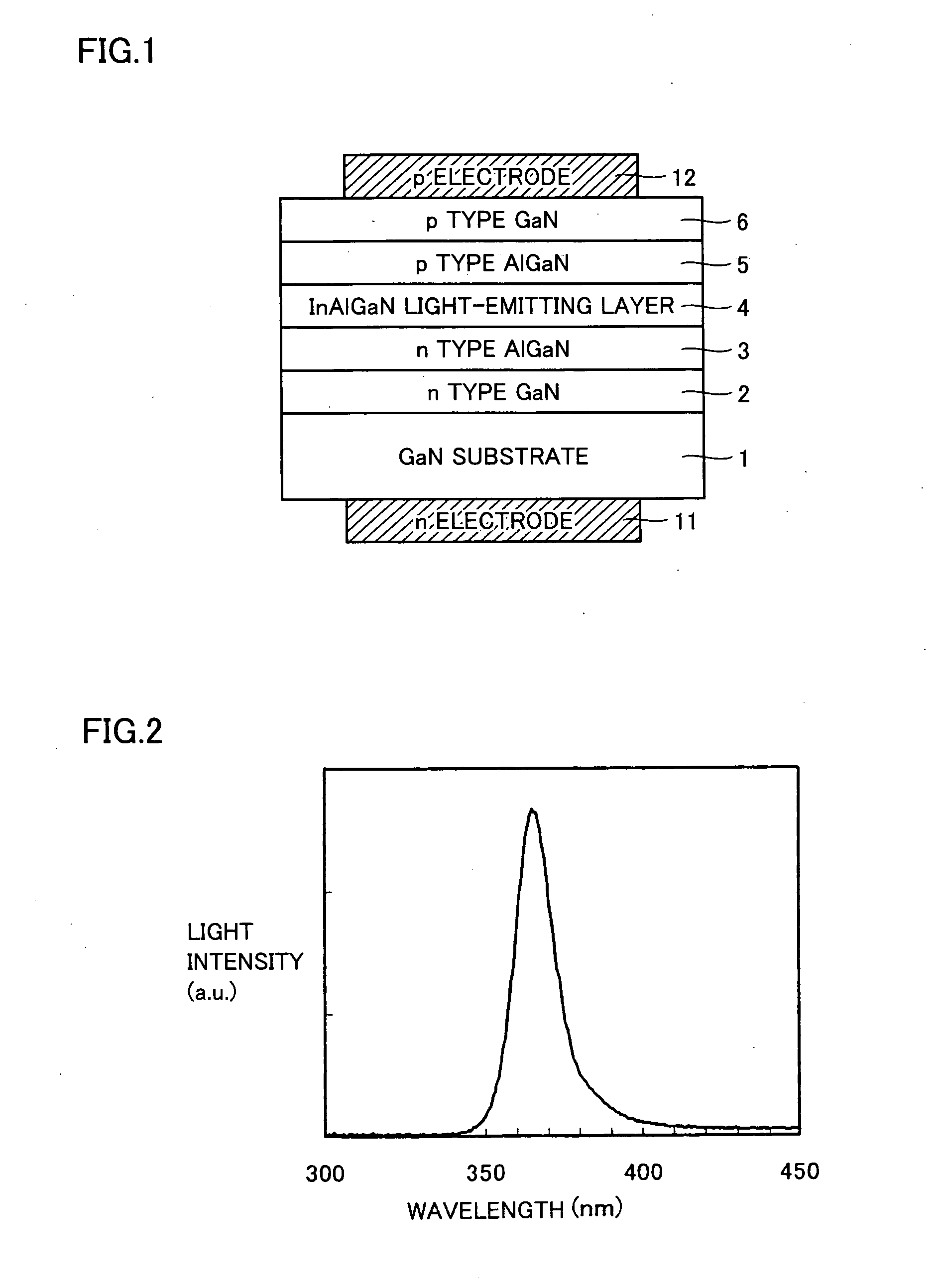
[0028]FIG. 1 shows an LED according to a first embodiment of the present invention. In FIG. 1, a stacked structure (an n type GaN layer 2 / an n type AlxGa1-xN layer 3 / an InAlGaN light-emitting layer 4 / a p type AlxGa1-xN layer 5 / a p type GaN layer 6) is formed on a GaN substrate 1. An n electrode 11 is arranged on a second main plane, that is, a backside of GaN substrate 1, while a p electrode 12 is arranged on p type GaN layer 6. Ultraviolet light is emitted from the InAlGaN light-emitting layer by applying a current to the pair of n electrode 11 and p electrode 12. The InAlGaN light-emitting layer has a composition of InxaAlyaGa1-xa-yaN.
[0029] The GaN-based LED shown in FIG. 1 is manufactured by the following processing steps. A GaN substrate having thickness of 400 Em, a dislocation density of 5E6 cm−2 and a resistivity of 1E—2 Ωcm was arranged on a susceptor within an MOCVD (Metal Organic Chemical Vapor Deposition) device. While the inside of the depositi...
second embodiment
[0034] (Second Embodiment)
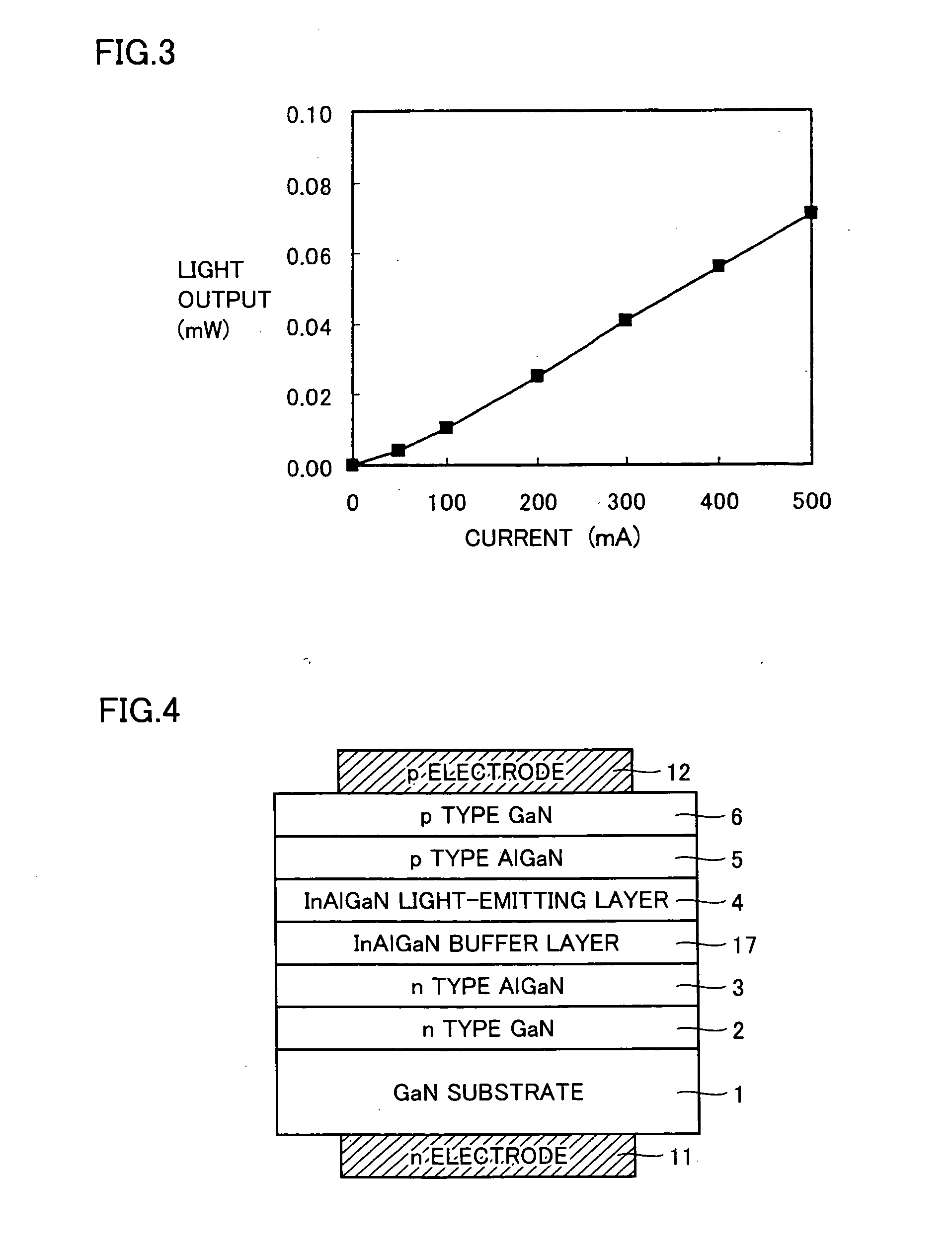
[0035]FIG. 4 shows an ultraviolet light-emitting diode according to a second embodiment of the present invention. As compared with the stacked structure of the ultraviolet LED shown in FIG. 1, this ultraviolet light-emitting diode is characterized in that, an InxAlyGa1-x-yN layer 17 as a buffer layer is arranged in contact with light-emitting layer 4 on a side nearer to GaN substrate 1. In addition, the light-emitting layer has a multiple quantum well structure, which will be described below.
[0036] A manufacturing method of the ultraviolet LED according to this embodiment is as follows. A substrate having thickness of 400 μm and a threading dislocation density of 5E61 cm2 was used as GaN substrate 1. N type GaN layer 2 and n type AlxGa1-xN layer 3 were successively formed on GaN substrate 1 by a method similar to that in the first embodiment. Then, InxAlyGa1-x-yN buffer layer 17 having thickness of 50 nm was grown at a growth temperature of 830° C. in cont...
third embodiment
[0042] (Third Embodiment)
[0043] In a third embodiment of the present invention, light outputs were compared between an ultraviolet LED formed on the GaN substrate (an example of the present invention) and an ultraviolet LED formed on a GaN template (a substrate formed by growing an n type GaN for 3 μm on a sapphire substrate via a GaN buffer layer grown at low temperature) (an comparative example). The GaN template used was made previously. Both of the aforementioned example of the present invention and comparative example were formed to have stacked structures as shown in FIGS. 4 and 5 except that, as a backside of the GaN template is an insulator, the n electrode for the GaN template was formed on the previously exposed n type GaN layer.
[0044] For manufacturing, both GaN substrate and GaN template were arranged together on the susceptor within the MOCVD device. Then, the n type GaN layer, n type Alx1Ga1-x1N layer and InxAlyGa1-x-yN layer as a buffer layer were formed on each of t...
PUM
| Property | Measurement | Unit |
|---|---|---|
| threading dislocation density | aaaaa | aaaaa |
| thickness | aaaaa | aaaaa |
| thickness | aaaaa | aaaaa |
Abstract
Description
Claims
Application Information
 - R&D
- Intellectual Property
- Life Sciences
- Materials
- Tech Scout
- Unparalleled Data Quality
- Higher Quality Content
- 60% Fewer Hallucinations
Browse by: Latest US Patents, China's latest patents, Technical Efficacy Thesaurus, Application Domain, Technology Topic, Popular Technical Reports.
© 2025 PatSnap. All rights reserved.Legal|Privacy policy|Modern Slavery Act Transparency Statement|Sitemap|About US| Contact US: help@patsnap.com


