Display device and electronic appliance

a display device and electronic appliance technology, applied in the field of display devices, can solve the problems of difficult display of impressive images, and achieve the effects of reducing weight, thickness and size of display devices, and forming thinner

Active Publication Date: 2005-02-24
SEMICON ENERGY LAB CO LTD
View PDF4 Cites 92 Cited by
  • Summary
  • Abstract
  • Description
  • Claims
  • Application Information

AI Technical Summary

Benefits of technology

[0020] According to the invention, a display with a larger screen can be mounted in a display device and a portable information terminal that have been limited in screen size. In addition, since dual display is achieved by using a dual display panel, a display device itself can be formed thinner than that using two single display panels. Therefore, a higher added value of a display device and a portable information terminal can be realized while reducing the weight, thickness and size thereof.

Problems solved by technology

However, an existing display has a small screen which is seen with difficulty, therefore, impressive images are not displayed easily.

Method used


Image

  • Display device and electronic appliance
  • Display device and electronic appliance
  • Display device and electronic appliance

Examples


embodiment mode 1

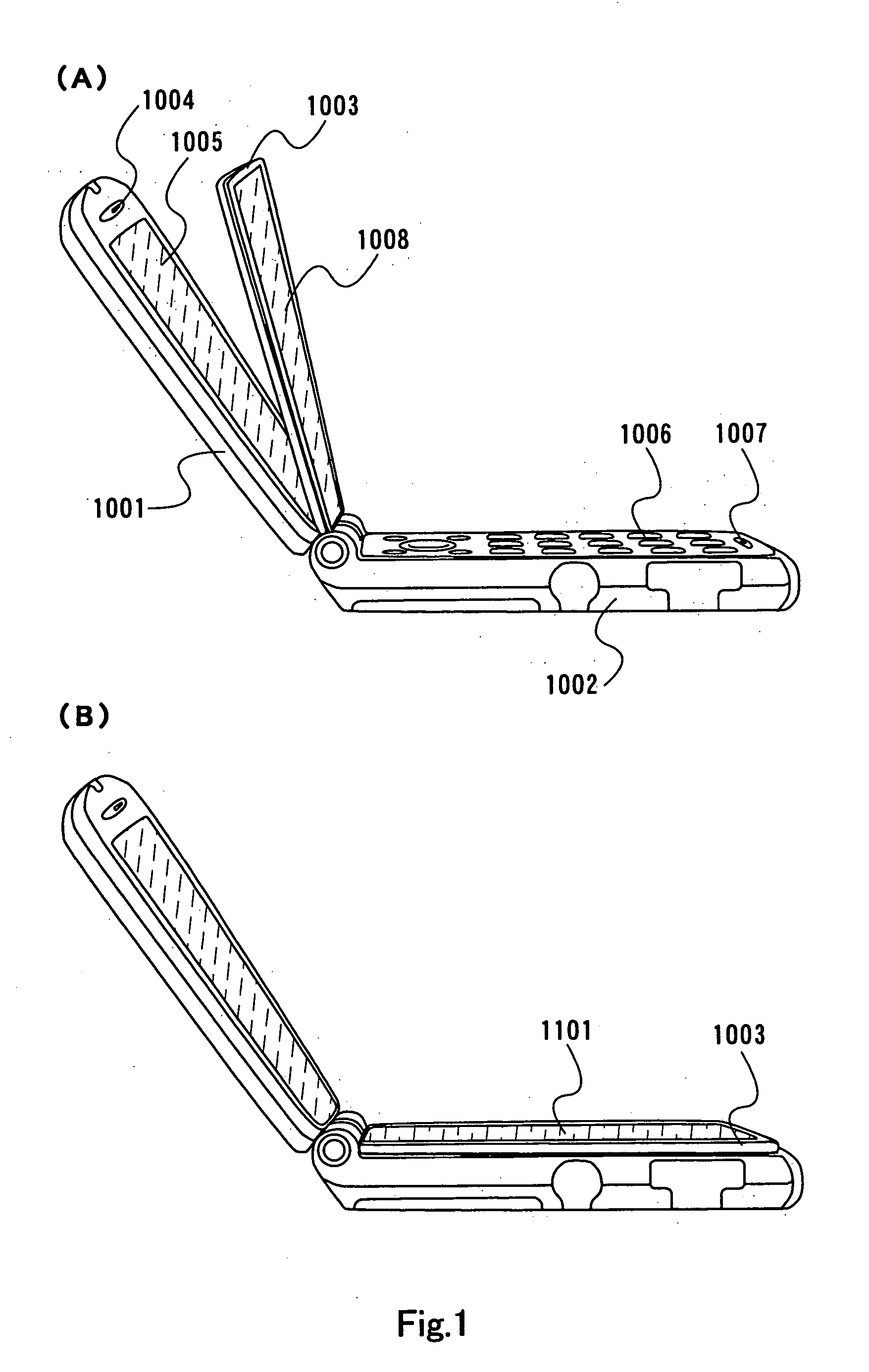
[0029]FIG. 1 shows an example of a flip phone including a dual display panel 1003.

[0030] The flip phone comprises a first housing 1001, a second housing 1002 and a dual display panel 1003. The first housing 1001 includes an audio output portion 1004, a first display screen 1005 and the like, and the second housing 1002 includes an operating button 1006, an audio input portion 1007 and the like. The dual display panel 1003 includes a second display screen 1008, a third display screen 1101 and the like.

[0031] According to the invention, the dual display panel 1003 is disposed between the first housing 1001 and the second housing 1002 of the mobile phone. When the dual display panel 1003 overlaps the first housing 1001, the second display screen 1008 of the dual display panel 1003, namely, only a single display screen is used. When the dual display panel 1003 overlaps the second housing 1002, the third display screen 1101 of the dual display panel 1003 and the first display screen 10...

embodiment mode 2

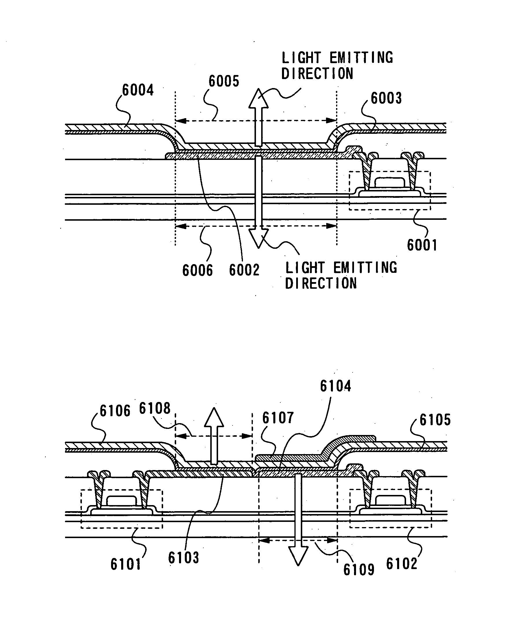
[0038] In Embodiment Mode 2, a dual light emission panel having a first display screen and a second display screen is described. Note that in this specification, a pixel electrode or a counter electrode using a light transmitting material means a transparent conductive film such as ITO or a film using aluminum and the like formed with a thickness that allows light to transmit through it, and a reflective material means a conductive material using aluminum and the like, which reflects light.

[0039]FIG. 6A comprises a driving TFT 6001, a pixel electrode 6002 using a light transmitting material, an EL layer 6003, a counter electrode 6004 using a light transmitting material, a first display area 6005, a second display area 6006 and the like.

[0040] A current flows between the pixel electrode 6002 connected to the driving TFT 6001 and the counter electrode 6004, and thereby the EL layer 6003 in the first display area 6005 emits light. At this time, since the pixel electrode 6002 and the ...

embodiment 1

[0055] An example of a display module portion of the invention is explained with reference to FIG. 3.

[0056] A signal control circuit 3001 comprises a CPU 3002, a memory A 3003, a memory B 3004, a memory controller 3005 and the like. A dual display panel 3007 comprises a first source signal line driver circuit 3008, a first gate signal line driver circuit 3009, a first display screen 3010, a second display screen that is on the back side of the first display screen, and the like. A display panel 3011 comprises a second source signal line driver circuit 3012, a second gate signal line driver circuit 3013, a third display screen 3014 and the like.

[0057] In a first display state, a switch 3015 is turned off. A signal and a driving voltage for operating the dual display panel 3007 are inputted from a display controller 3006 to the first source signal line driver circuit 3008, the first gate signal line driver circuit 3009 and the like. Since the switch 3015 is off at this time, the dis...


PUM


Abstract

A dual light emission panel (panel capable of displaying images on both screens) is mounted in a display device or a portable information terminal to achieve a module with a small volume. The display device of the invention comprises a display screen, a first housing and a second housing that are connected to each other, and a dual light emission panel including display screens each on the front side and the back side. The dual light emission panel is connected to the first housing, disposed between the first housing and the second housing when overlapping the first housing, and rotated around a connecting point of the dual light emission panel and the first housing.

Description

TECHNICAL FIELD [0001] The present invention relates to a display device having a light emitting element, and more particularly relates to a portable information terminal such as a mobile phone and a PDA (Personal Digital Assistant). BACKGROUND ART [0002] In recent years, as a light emitting device, a display device using a self-light emitting element typified by an electro-luminescence (EL) element and the like has been studied and developed instead of a liquid crystal display (LCD) using a liquid crystal element for a pixel. Such a light emitting device has the advantages of high image quality and wide viewing angle because of a light emitting type, and reduced thickness and weight and the like without need of a back light. Thus, the light emitting device is expected to be widely used for a display screen of a mobile phone and a display device. [0003] As for a portable information terminal, a high added value is required with diversification of uses. Recently, a display can be use...

Claims


Application Information

Patent Timeline
Patent Type & Authority Applications(United States)
IPC IPC(8): G06F1/16G06F3/14H04M1/02
CPCG06F1/1616G06F1/1637G06F1/1647G06F1/1652H04M2250/16H04M1/0214H04M1/0247H04M1/0266G06F3/1423G06F1/00G09F9/30H05B33/00H05B33/14
Inventor OSAME, MITSUAKIANZAI, AYAYAMAZAKI, SHUNPEI
Owner SEMICON ENERGY LAB CO LTD
Why Eureka
Try Eureka