Phase change thermal interface materials including polyester resin

a thermal interface and phase change technology, applied in the direction of electrical apparatus and process, electrical contruction details, semiconductor/solid-state device details, etc., can solve the problems of bulk thermal conductivity of these materials, insufficient reliability-stressing test, and greases migrating out of between the interfaces

Inactive Publication Date: 2005-02-24
INTEL CORP
View PDF12 Cites 49 Cited by
  • Summary
  • Abstract
  • Description
  • Claims
  • Application Information

AI Technical Summary

Problems solved by technology

However, metal filled epoxies exhibit localized phase separation due to package thermo-mechanical behavior and their high modulus leads to delamination at the interfaces.
However, greases tend to migrate out from between the interfaces under cyclical stresses encountered during temperature cycling, a phenomenon known as “pump out.”
Their modulus (E′) is low enough so that the material can still dissipate internal stresses and prevent interfacial delamination, but not low enough to survive the reliability-stressing test.
However, from a formulation point, the polymer and filler combinations that have been utilized in PCMs restrict the bulk thermal conductivities of these materials.
In general pump-out, bleed-out, and dry-out are continuing reliability issues for phase change TIMs.
This presents a high risk for thermo-oxidative degradation over time at operating temperatures below about 110° C. and is a show-stopper for applications with operating temperatures above 110° C.

Method used


Image

  • Phase change thermal interface materials including polyester resin
  • Phase change thermal interface materials including polyester resin
  • Phase change thermal interface materials including polyester resin

Examples


example 1

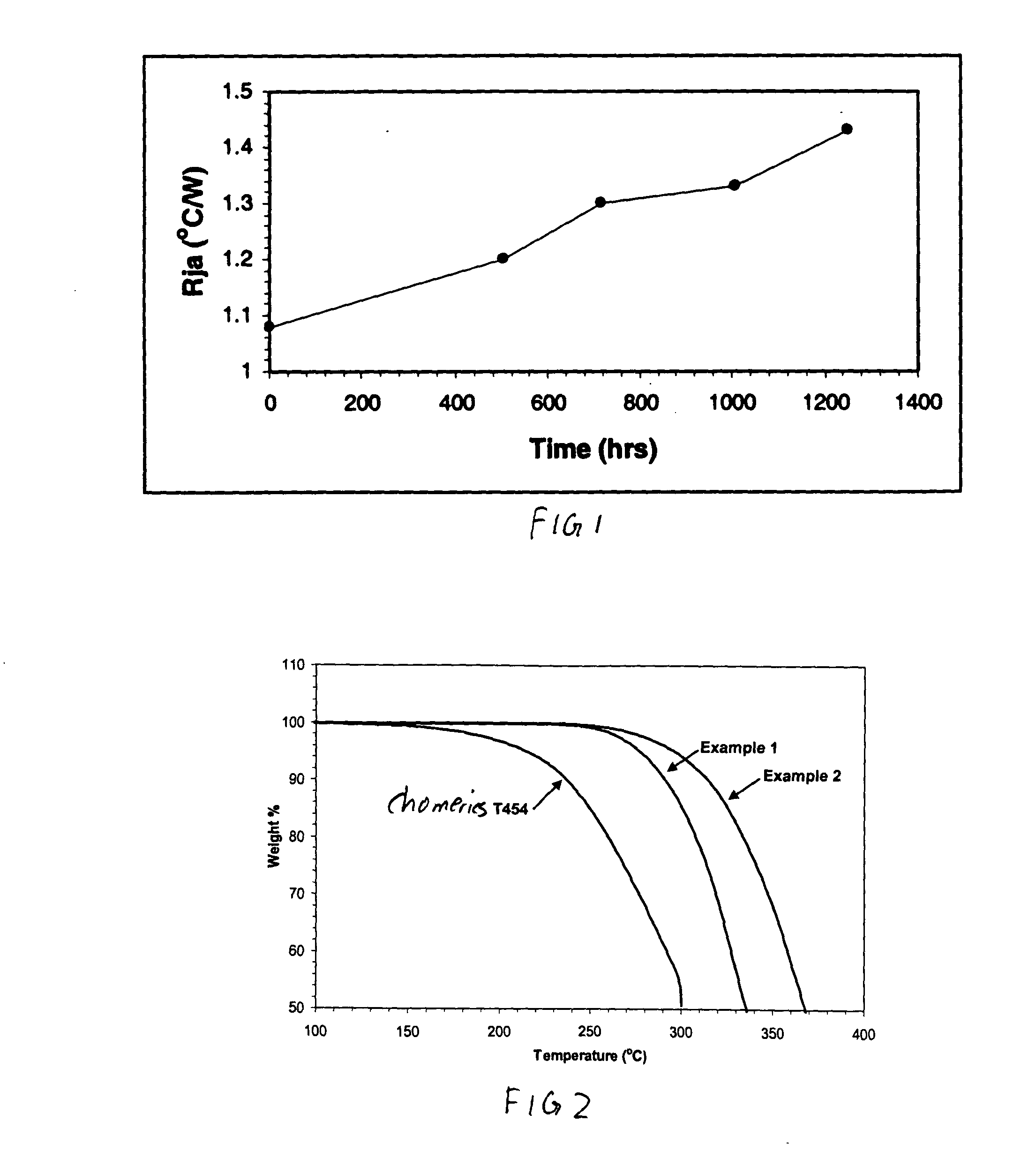
This example is representative of a polyester-based phase change thermal interface material that has significantly improved thermo-oxidative stability: 50 grams of toluene, 50 grams of polycaprolactone (POLYOL 1278® from Dow Chemical Company, Inc.) with a melting point of 50° C., and 50 grams of BN are mixed at 80° C. in a Ross double planetary mixer for 3 hrs. The material is cast onto 3-mil thick Mylar® film and dried at 100° C. to a final thickness of about 13 mils. The material is evaluated by an interfacial tester at 90 psi and 90° C. and found to have a thermal resistance of 0.1° C. cm2 / W. As illustrated in FIG. 2, TGA analysis in air shows that the material begins to degrade above about 200° C., with significant degradation occurring after about 300° C.

example 2

This example is representative of a polyester organoclay nanocomposite-based phase change thermal interface material that has significantly improved thermo-oxidative stability: 50 grams of toluene, 49 grams of polycaprolactone (POLYOL 1278® from Dow Chemical Company, Inc.) with a melting point of 50° C., 49 grams of BN, and 2 grams of organoclay (Nanomer® I.30 P from Nanocor, Inc.) are mixed at 80° C. in a Ross double-planetary mixer for 3 hours. The material is cast onto 3-mil-thick Mylar® film and dried at 100° C. to a final thickness of about 13 mils. The material is evaluated by an interfacial tester at 90 psi and 90° C. and found to have a thermal resistance of 0.1° C. cm2 / W. As illustrated in FIG. 2, TGA analysis in air shows that the material begins to degrade above about 200° C., with significant degradation occurring after about 320° C.


PUM

PropertyMeasurementUnit
melting pointaaaaaaaaaa
diameteraaaaaaaaaa

Abstract

An embodiment of a phase change TIM of this invention comprises a polyester matrix with melting temperature near or below operating temperature (typically less than about 130° C.), thermally conductive filler with bulk thermal conductivity greater than about 50 W/mK, and optionally other additives. The polyester resin has improved thermo-oxidative stability compared to the polyolefin resins, thereby providing improved reliability performance during test.

Description

BACKGROUND OF THE INVENTION 1). Field of the Invention This invention relates to phase change thermal interface materials (TIM's) comprising polyester resins and electronic devices with such TIM's. 2). Discussion of Related Art Today's semiconductor devices, whether discrete power or logic integrated circuits, are smaller, run faster, do more and generate more heat. Due to increased power, some desktop microprocessors dissipate heat in the range of 50 to 100 watts. These power levels require thermal management techniques involving large-capacity heat sinks, good air flow, and careful management of thermal interface resistances. A well-designed thermal management program will keep operating temperatures within acceptable limits in order to optimize device performance and reliability. Semiconductor devices are kept within their operating temperature limits by transferring junction-generated waste heat to the ambient environment, such as the surrounding room air. This is best acco...

Claims


Application Information

Patent Timeline
Patent Type & Authority Applications(United States)
IPC IPC(8): C09K5/06H01L23/373H01L23/427
CPCC09K5/063H01L23/3737H01L23/4275H01L2924/0002H01L2224/8385H01L2224/32245H01L24/29H01L2224/2929H01L2224/293H01L2224/29386H01L2924/00H01L2924/14H01L21/56H01L23/02H01L23/06H01L23/28
Inventor MATAYABAS, JAMES CHRISTOPHER JR.KONING, PAUL A.
Owner INTEL CORP
Why Eureka
Try Eureka