Vacuum arc evaporation apparatus and method, and magnetic recording medium formed thereby

a vacuum arc and evaporation apparatus technology, applied in vacuum evaporation coatings, magnetic recording layers, coatings, etc., can solve the problems of difficult to provide a cooling mechanism for the magnetic material, difficult to maintain stably the arc discharge, and difficult to discharge the cathode material plasma beam pb toward the desired direction, etc., to achieve high hardness

Inactive Publication Date: 2005-03-03
FUJI ELECTRIC DEVICE TECH CO
View PDF14 Cites 43 Cited by
  • Summary
  • Abstract
  • Description
  • Claims
  • Application Information

AI Technical Summary

Benefits of technology

[0010] The discharge vacuum chamber can have a tubular shape and can be provided with an insulating material between the inner surface of the discharge vacuum chamber and the first generating unit. The apparatus can include a cooling unit for preventing the cathode target, the first generating unit, and the discharge vacuum chamber from being overheated by the arc discharge.
[0011] The deposition material can be carbon. The substrate can include a magnetic recording layer. When the carbon is deposited on the magnetic recording layer, it forms an overcoat layer having a tetrahedral amorphous carbon structure with a high hardness.

Problems solved by technology

At the arc source Sa in the above arrangement, with the deposition material taken as a cathode target 16, a vacuum arc discharge is induced between the cathode target 16 and an anode 17 by contacting a striker 15 with the surface of the cathode target 16 to thereby generate the cathode material plasma P. However, with this arrangement, it is difficult to stably maintain the arc discharge.
Moreover, another problem is that a cathode spot of the discharge circumvents the cathode target 16, making it difficult to discharge the cathode material plasma beam Pb toward the desired direction.
Furthermore, in the arrangement disclosed in the latter reference, it is difficult to provide a cooling mechanism for the magnetic material.

Method used


Image

  • Vacuum arc evaporation apparatus and method, and magnetic recording medium formed thereby
  • Vacuum arc evaporation apparatus and method, and magnetic recording medium formed thereby
  • Vacuum arc evaporation apparatus and method, and magnetic recording medium formed thereby

Examples


Embodiment Construction

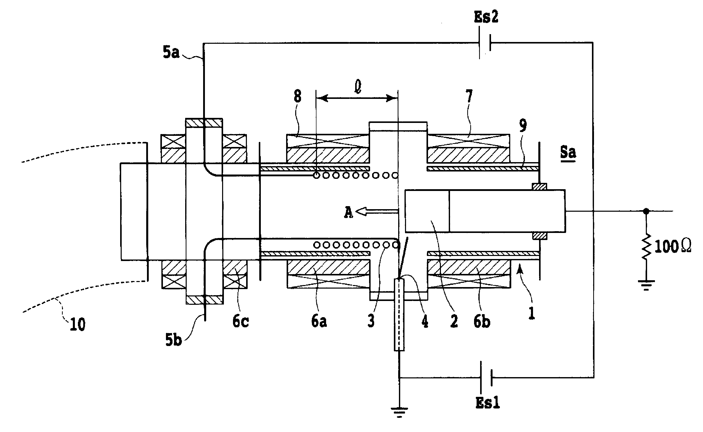
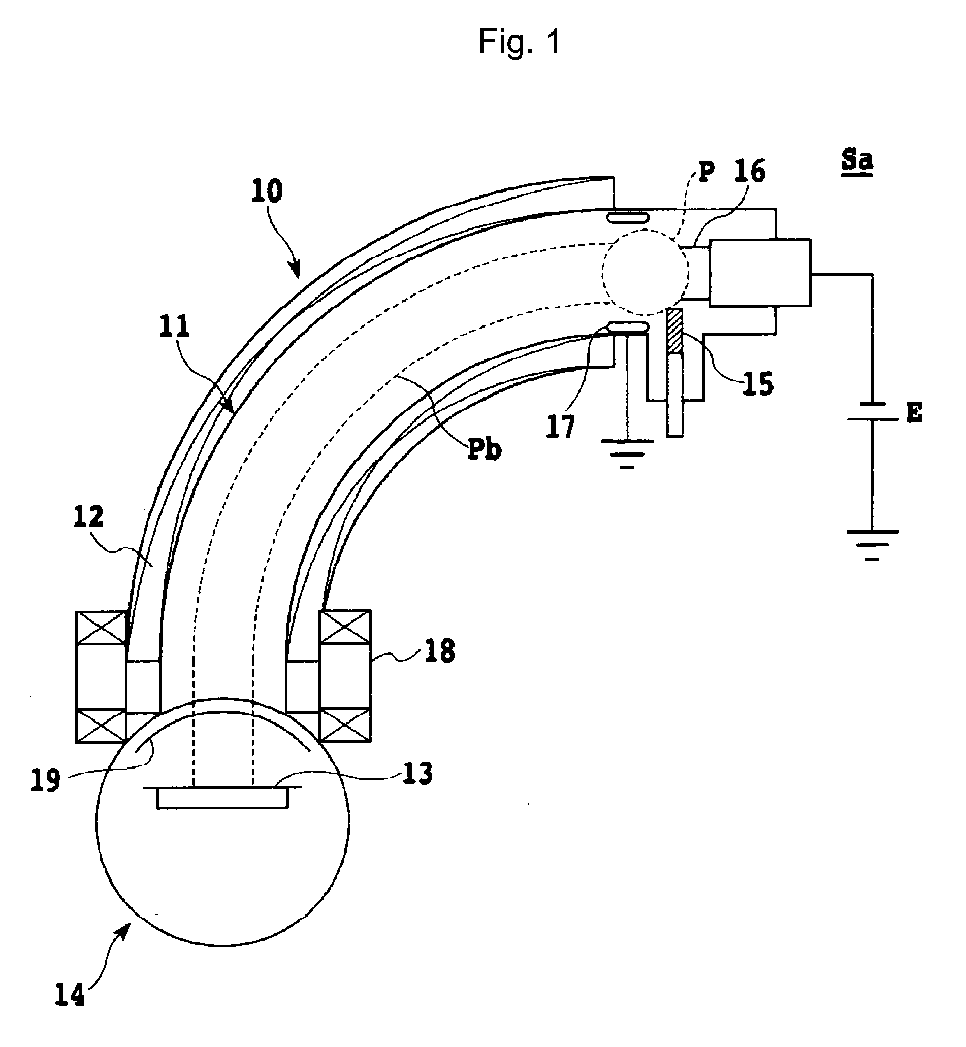
[0017] The present vacuum arc evaporation apparatus can include a deposition vacuum chamber 14, a discharge unit Sa for discharging arc from a cathode target 2, which is made of a deposition material for depositing on a substrate disposed in the deposition vacuum chamber, and a plasma guiding unit 10 disposed between the deposition vacuum chamber and the discharge unit for guiding the cathode material plasma generated by the arc discharge to the deposition vacuum chamber by an induced magnetic field, which can be generated by feeding a current to a coil of the plasma guiding unit, to deposit the cathode target on the substrate.

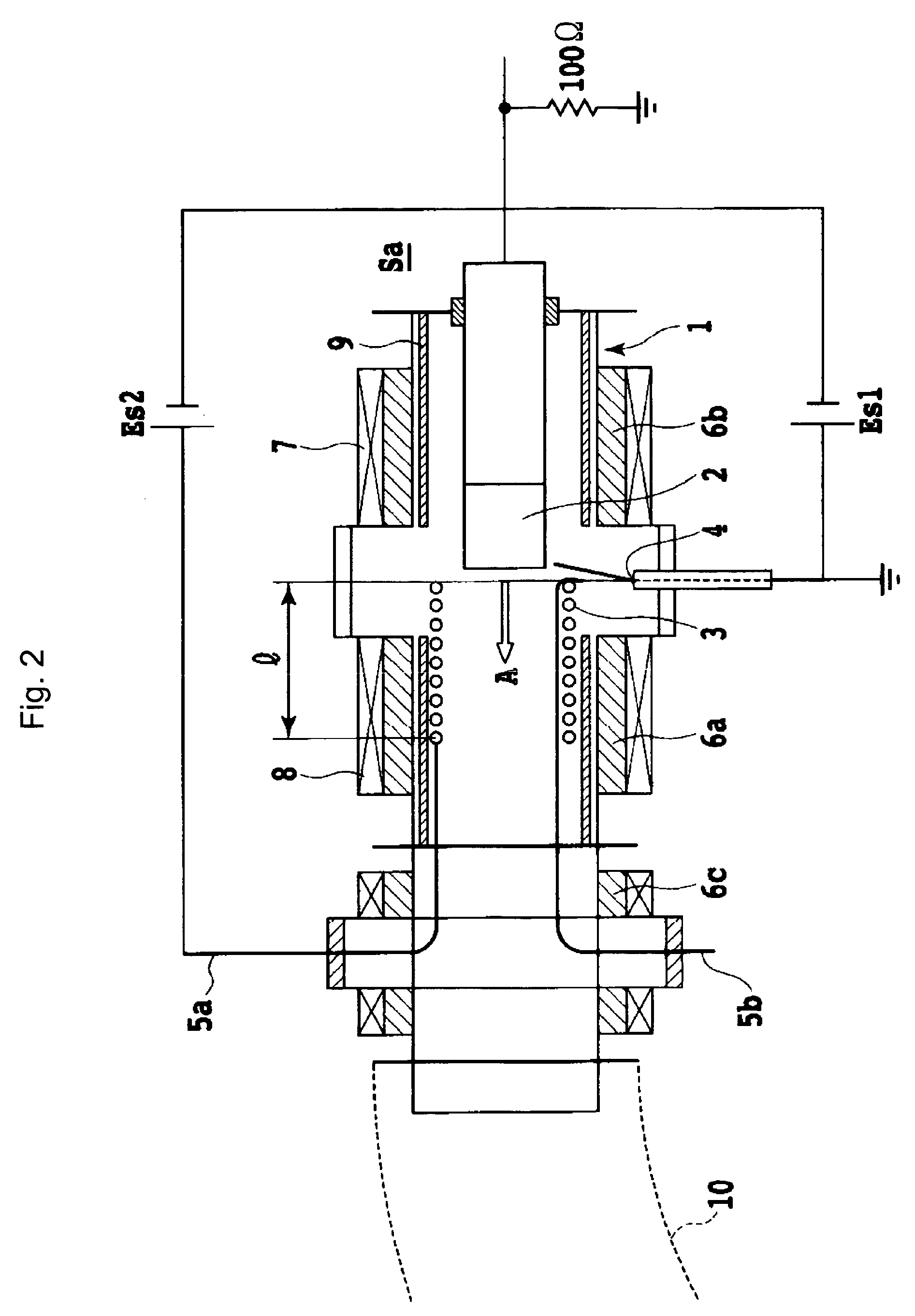
[0018] Referring to FIG. 2, the discharge unit can include an arc source discharge vacuum chamber 1 containing the cathode target 2. The discharge vacuum chamber is electrically grounded while the cathode target 2 is electrically ungrounded and made of the deposition material. An anode 3, which is also electrically ungrounded, can be provided as a first gener...


PUM

PropertyMeasurementUnit
inner diameteraaaaaaaaaa
lengthaaaaaaaaaa

Abstract

In a vacuum arc evaporation apparatus, to stably maintain vacuum arc discharge at an arc source when depositing a cathode material on a substrate, namely a magnetic recording medium, an ungrounded anode of a coil-type tube is placed inside an arc source discharge vacuum chamber. A DC arc power supply is connected between the cathode and the anode to cause an arc current to flow in the anode to generate a first magnetic field in one direction, from the cathode toward the anode. A second magnetic field is generated in the opposite direction, from the anode to the cathode by feeding a specified current to an external coil positioned around the discharge chamber. The external coil includes an around-cathode coil and an around-anode coil. The arc discharge can be started by operating a striker to carry out the deposition.

Description

BACKGROUND [0001] A diamond-like carbon (DLC) film, formed of carbon, is suitable for a wear or abrasive resistant layer of a magnetic recording medium because it has an excellent surface smoothness and a high hardness. Such a hard coating has been typically formed via a sputtering method, a plasma CVD method, or a vacuum arc evaporation method. FIG. 1 illustrates an example of an arrangement of a filtered cathodic arc (FCA) evaporation apparatus currently used in a vacuum arc evaporation method. [0002] In the example of the arrangement in FIG. 1, a cathode material plasma P is generated at an arc source Sa. With the use of a magnetic filter 10, the plasma P is guided as a cathode material plasma beam Pb to a substrate 13, which is held in a deposition vacuum chamber 14 having a shutter 19. The magnetic filter 10 has a stainless steel pipe 11 bent in a quarter circular-arc-shape as a core, on which an electromagnet coil 12 is provided. Between the magnetic filter 10 and the depositi...

Claims


Application Information

Patent Timeline
Patent Type & Authority Applications(United States)
IPC IPC(8): C23C14/24G11B5/72G11B5/84H01J37/32
CPCH01J37/3266H01J37/32055
Inventor NAGATA, NARUHISA
Owner FUJI ELECTRIC DEVICE TECH CO
Why Eureka
Try Eureka