Interference scatterometer

a scatterometer and interference technology, applied in the field of optical scatterometers, can solve the problems of not being able to measure the specular reflectivity amplitude, the inability of current scatterometers to simultaneously measure scattering data at multiple angles and wavelengths, and the inability to use the spectrum reflectivity amplitude and illumination angles to measure the effect of intensity

Active Publication Date: 2005-03-03
ZYGO CORPORATION
View PDF4 Cites 31 Cited by
  • Summary
  • Abstract
  • Description
  • Claims
  • Application Information

AI Technical Summary

Benefits of technology

to provide a scatterometer system that enables multiple illumination angles to be measured simultan

Problems solved by technology

Current scatterometers are not capable of simultaneously measuring scattering data at multiple angles and wavelengths.
This technology cannot eliminate the confusion regarding which illumination angle caused scattering into which output angle, and therefore it cannot be used to measure the specular reflectivity amplitudes for a non-specular object like a diffraction grating without limiting in some way the illumination angles.
This is a broad scatterometry patent utilizing reflectometry, but it does not include an interference microscope or provide for measurement of interference images of a back focal plane from which can be deduced the specular reflection

Method used


Image

  • Interference scatterometer
  • Interference scatterometer
  • Interference scatterometer

Examples


Embodiment Construction

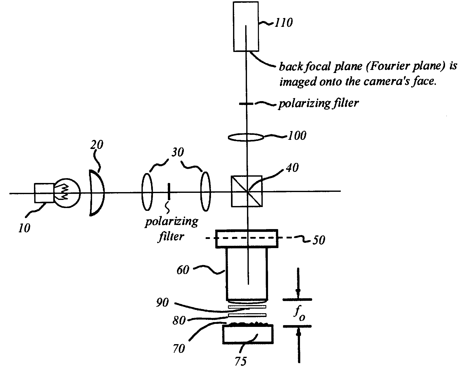
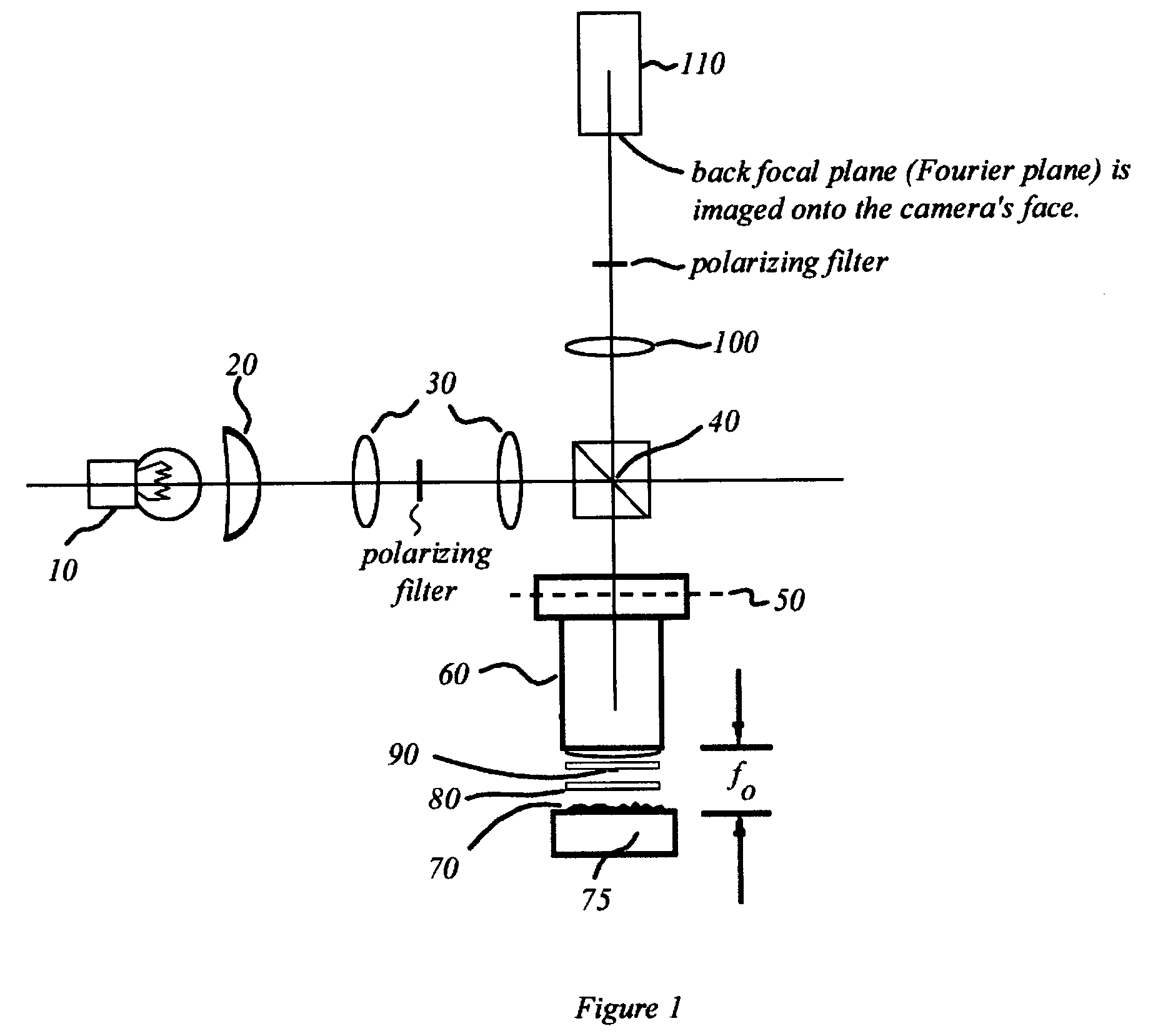
FIG. 1 is an illustration of a Mireau interference microscope adapted in accordance the present invention. A light source 10 provides broadband illumination for the microscope. Light source 10 is a highly incoherent luminous source such as an arc lamp or a tungsten halogen lamp. Light source 10 is directed to and imaged on back focal plane 50 of microscope objective lens 60 by condenser lens 20, lenses 30, and beamsplitter 40.

Imaging a highly incoherent light source on back focal plane 50 in this manner provides a type of illumination known as Koehler illumination to the back focal plane 50 of the microscope. Koehler illumination is characterized by a minimum of spatial coherence between any two points on back focal plane 50. That is, in Koehler illumination, the mutual coherence function is nearly zero for any spaced-apart two points on back focal plane 50.

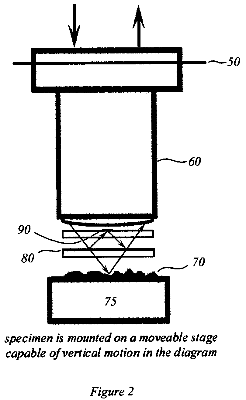
The optical reference path of the Mireau interference microscope is shown in FIG. 1 and again, in more detail, in FIG. 2. Th...


PUM


Abstract

An interference spectroscopy instrument provides simultaneous measurement of specular scattering over multiple wavelengths and angles. The spectroscopy instrument includes an interference microscope illuminated by Koehler illumination and a video camera located to image the back focal plane of the microscope's objective lens while the path-length difference is varied between the reference and object paths. Multichannel Fourier analysis transforms the resultant intensity information into specular reflectivity data as a function of wavelength. This multitude of measured data provides a more sensitive scatterometry tool having superior performance in the measurement of small patterns on semiconductor devices and in measuring overlay on such devices.

Description

FIELD OF THE INVENTION The present invention relates to field of optical scatterometry. More particularly, the present invention combines an interference microscope with Fourier transform spectroscopy to provide a multi-channel spectroscopy instrument for simultaneously measuring light reflected from multiple illumination angles at a plurality of wavelengths. The invention has particular applicability in the testing of semiconductor devices. BACKGROUND Scatterometry is an optical technique which uses the optical properties of scattered light to determine physical attributes of a sample. More specifically, scatterometry is used in the field of semiconductor testing to monitor the line width and line shape of patterns on semiconductor wafers. This is accomplished by forming a test structure including an array of lines on the semiconductor wafer. Typically the test structure is a diffraction grating some tens of microns on a side, but other structures can be used. Light is directed t...

Claims


Application Information

Patent Timeline
IPC IPC(8): G01J3/453G01N21/956G03F7/20
CPCG01J3/453G03F7/70633G01N21/95684
Inventor DAVIDSON, MARK P.
Owner ZYGO CORPORATION
Why Eureka
Try Eureka