Method of manufacturing a fuel cell array and a related array

Inactive Publication Date: 2005-03-03
MTI MICROFUEL CELLS
View PDF20 Cites 18 Cited by
  • Summary
  • Abstract
  • Description
  • Claims
  • Application Information

AI Technical Summary

Benefits of technology

[0018] The deficiencies and disadvantages of prior techniques have been overcome by the solutions provided by the present invention, which is a process for manufacturing a fuel cell and an associated fuel cell array that includes a unique lead frame that integrates current collectors and other components of the fuel cell that are inserted into a mold and thereby sealed. More specifically, the fuel cell components are assembled on a lead frame structure, which is used to facilitate the molding process. The lead frame, containing the previously assembled components of the fuel cell, is inserted into a mold cavity formed by the mold plate

Problems solved by technology

However, because fuel processing is complex, and requires expensive components, which occupy comparatively significant volume, the use of reformer based systems is presently limited to comparatively large, high power applications.
The overall reaction may be limited by the failure of either of these reactions to proceed at an acceptable rate (more specifically, slow oxidation of the fuel mixture will limit the cathodic generation of water, and vice versa).
Such components themselves can be expensive because they are specially machined.
Furthermore, the assembly of devices that include these fasteners is a time consuming manual process that can al

Method used


Image

  • Method of manufacturing a fuel cell array and a related array
  • Method of manufacturing a fuel cell array and a related array
  • Method of manufacturing a fuel cell array and a related array

Examples


Embodiment Construction

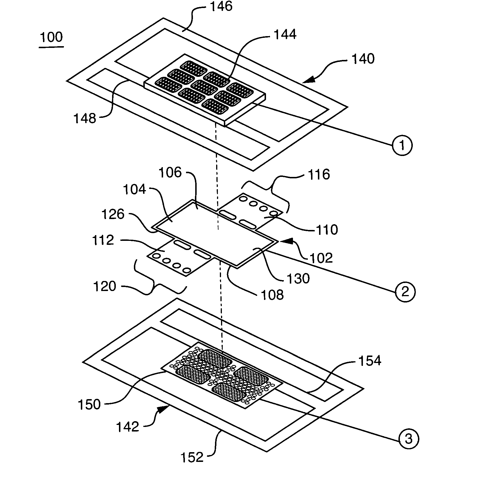
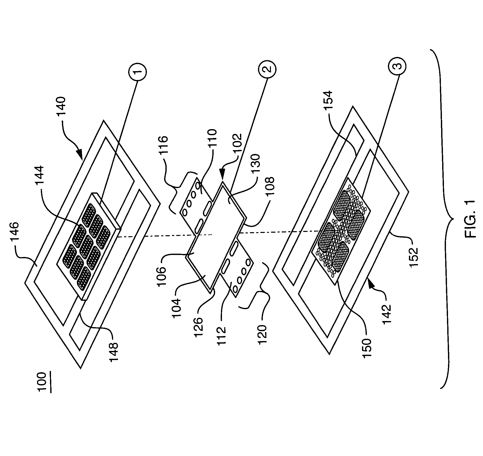
[0036]FIG. 1 is an exploded perspective view of a lead frame assembly and other components of the fuel cell fabricated in accordance with one aspect of the invention. More specifically, the lead frame assembly 100 includes a membrane electrode assembly (MEA) 102. The MEA 102 typically includes a catalyzed membrane electrolyte 104, which may include a protonically conductive, electronically non-conductive membrane. One material that may be used for the catalyzed membrane, which is commercially available is NAFION®, a registered trademark of E.I. Dupont de Nemours and Company, a cation exchange membrane based on a polyperflourosulfonic acid in a variety of thicknesses and equivalent weights. The membrane is typically coated on each of its major surfaces with an electrocatalyst such as platinum or a platinum / ruthenium mixture or alloyed particles (not shown). Thus, it is referred to herein as the “catalyzed membrane electrolyte, or the “catalyst coated membrane” (CCM). One face of the ...


PUM

PropertyMeasurementUnit
Flow rateaaaaaaaaaa
Moldableaaaaaaaaaa

Abstract

A process for fabrication and molding of a fuel cell, or an array of fuel cells is provided. The inventive process, in accordance with one aspect of the invention, includes diffusion layers being hot-press bonded onto current collectors. A catalyzed membrane is sandwiched between two current collectors integrated into the lead frames designed for use in a molding process. A raised surface on each current collector provides a means for shut off of the mold plates. A suitable moldable material is introduced into a mold cavity to form a frame around the current collectors, which provides a tight and secure seal, eliminating the need for gasketing, and which further also provides compression thus further eliminating screws, nuts and other fasteners.

Description

BACKGROUND OF THE INVENTION [0001] 1. Field of the Invention [0002] This invention relates generally to fuel cells, and more particularly, to the manufacture of such fuel cells. [0003] 2. Background Information [0004] Fuel cells are devices in which electrochemical reactions are used to generate electricity. A variety of materials may be suited for use as a fuel depending upon nature of the fuel cell. Organic materials, such as methanol or natural gas, are attractive fuel choices due to their high specific energy. [0005] Fuel cell systems may be divided into “reformer-based” systems (i.e., those in which the fuel is processed in some fashion to extract hydrogen from the fuel before it is introduced into the fuel cell) or “direct oxidation” systems in which the fuel is fed directly into the cell without the need for separate internal or external processing. Most currently available fuel cells are reformer-based fuel cell systems. However, because fuel processing is complex, and requi...

Claims


Application Information

Patent Timeline
IPC IPC(8): H01M8/02H01M8/10H01M8/24
CPCH01M8/0206H01M8/0247H01M8/0269Y02E60/521H01M8/2455H01M8/2465H01M8/1009Y02E60/50Y02P70/50H01M8/0273H01M8/242H01M8/2404
Inventor FANNON, MEGAN A.HIRSCH, ROBERT S.BECERRA, JUAN J.
Owner MTI MICROFUEL CELLS
Why Eureka
Try Eureka