[0021] In view of the foregoing conventional problems, an object of the present invention is to provide a battery which has an easily manufactured structure while realizing
high power output by eliminating parts such as a lead, cost reduction by reducing the number of parts and simplifying processes, and high capacity by increasing containment space for the electrode plate group in a battery case. Another object of the present invention is to provide a method for appropriately manufacturing this battery with
high productivity.
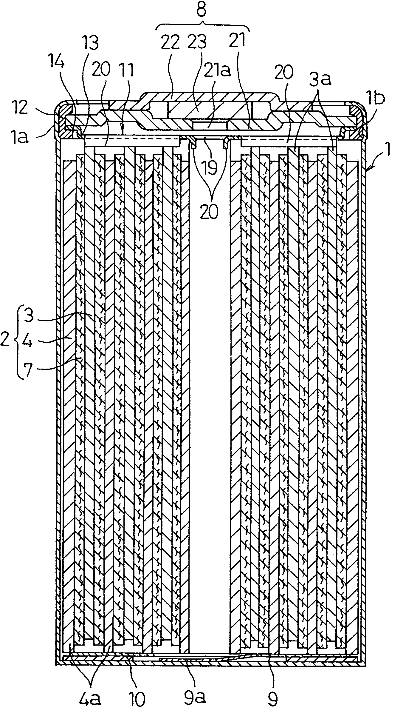
[0023] According to the battery of the present invention, since the flange-shaped collar section of the collector, which is tiered with a step, is directly connected to the periphery of the port sealing member, a positive electrode lead provided in a conventional battery is eliminated. Therefore, the
internal resistance of the battery is significantly reduced, and hence it is possible to obtain
high power output. In addition to the
elimination of the positive electrode lead, the battery case has the enlarged port section, and the battery has the insulating gasket which is set and held on the support rack section formed in the enlarged port section, so that a ring-shaped groove formed in the conventional battery becomes unnecessary. Accordingly, the volume of the electrode plate group can be increased by space which has occurred in a battery case of the conventional battery due to the existence of the positive electrode lead and the ring-shaped groove. Increase in the volume of the electrode plate group causes increase in the capacity of the battery. Also, in this battery, in addition to the
elimination of the positive electrode lead, an upper section insulating part, which has been provided in the conventional battery, becomes unnecessary because the ring-shaped groove is not formed. Thus, since the number of parts is reduced, and attachment processes of these unnecessary parts and a forming process of the ring-shaped groove are eliminated, it is possible to significantly reduce cost. Also the port sealing member and / or the collector of the one pole are horizontally clamped by the enlarged port section with the reduced
diameter in the battery case with the insulating gasket interposed therebetween. Therefore, the resistance to vibration and the resistance to
impact of the battery are significantly improved.
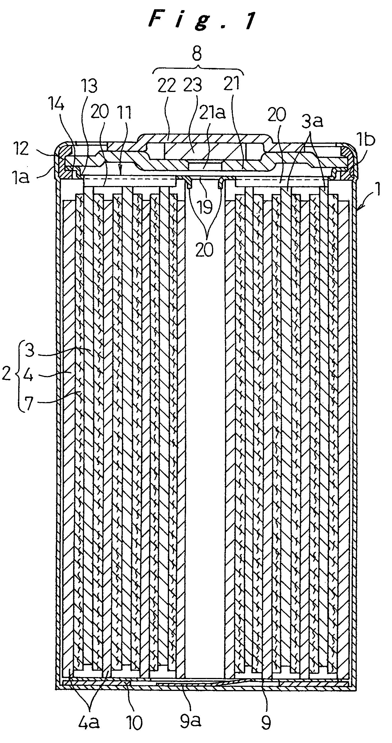
[0025] In the foregoing battery according to the present invention, since the collector of one pole has the smaller external
diameter than the filter portion of the port sealing member, and has the
welding rack section which is tiered with the step in the periphery thereof, it is possible to provide as many connecting sections as possible even if the flange-shaped collar section is omitted in the collector of one pole. Also, in this battery, only the periphery of the filter section of the port sealing member is held on the support rack section of the battery case with the insulating gasket interposed therebetween. Therefore, the
internal resistance of the battery is significantly reduced due to the elimination of a positive electrode lead, and hence it is possible to obtain high
power output, even if an existing gasket is used as the insulating gasket.
[0027] In the foregoing manufacturing method of the battery according to the present invention, it is possible to weld the flange-shaped collar portion of the collector to the periphery of the port sealing member, which is laminated on the flange-shaped collar portion of the collector, in a state that the collector is stably supported on the support rack section of the battery case with the insulating gasket interposed therebetween. Also, after the electrolytic solution is injected, the previously integrated port sealing member can be welded to the positive electrode collector by feeding a
welding current through the electrolytic solution. Therefore, it is possible to manufacture the battery with
high productivity.
[0029] In the foregoing manufacturing method of the battery according to the present invention, it is possible to easily weld the flange-shaped collar section of the positive electrode collector, which is welded to the electrode plate group, to the periphery of the filter section of the port sealing member in a state without attaching the insulating gasket by use of resistance
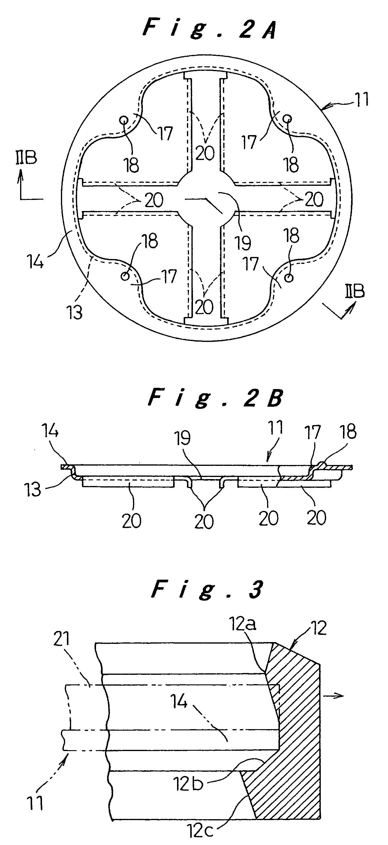
welding, directly without the medium of the electrolytic solution. Therefore, it is possible to firmly connect the positive electrode collector to the filter section with high welding quality by precisely carrying out welding. Also the insulating gasket is attached to the flange-shaped collar section of the positive electrode collector and the periphery of the filter section of the port sealing member, which are secured to each other by this welding, from above. The open end of the battery case is caulked, and the
diameter of the enlarged port section is reduced to firmly fix the periphery of the filter section and / or the flange-shaped collar section of the positive electrode collector with the insulating gasket interposed therebetween. In this state, the electrolytic solution is injected through the vent of the filter section and the opening of the positive electrode collector, and then the safety vent and the cap-shaped positive electrode terminal are attached to the filter section to assemble the port sealing member. Accordingly,
assembly processes are efficiently carried out due to improvement in the workability of every
assembly process. Therefore, it is possible to improve the productivity of the battery.

