Electromagnetic noise suppressor, structure with electromagnetic noise suppressing function, and method of manufacturing the same

a technology of electromagnetic noise and suppressor, which is applied in the direction of magnetic bodies, inductances, non-metallic protective coating applications, etc., can solve the problems of difficult stabilization of iron nitride crystal structure, inability to prove sufficient electromagnetic noise suppressing effect over the entire sub-microwave band, and increasing problems, so as to achieve convenient manufacturing, efficient suppression of electromagnetic noise, and easy structure manufacturing

Inactive Publication Date: 2006-02-23
SHIN-ETSU POLYMER CO LTD
View PDF10 Cites 34 Cited by
  • Summary
  • Abstract
  • Description
  • Claims
  • Application Information

AI Technical Summary

Benefits of technology

[0024] A method of manufacturing an electromagnetic noise suppressor of the present invention includes a vapor deposition process of physically vapor-depositing a magnetic material onto a binding agent to form a composite layer on the surface of the binding agent. Such a manufacturing method enables it to easily manufacture the electromagnetic noise suppressor of the present invention that has the composite layer constituted from the binding agent and the magnetic material integrated together.
[0025] A structure with an electromagnetic noise suppressing function of the present invention is a structure with at least a part of the surface thereof covered by the electromagnetic noise suppressor of the present invention. The structure with an electromagnetic noise suppressing function enables it to dispose the electromagnetic noise suppressor in a small space near a noise source and efficiently suppress electromagnetic noise in a sub-microwave band.
[0026] A method of manufacturing a structure with an electromagnetic noise suppressing function of the present invention includes a coating process of coating at least a part of the surface of the structure with a binding agent, and a vapor deposition process of physically vapor-depositing a magnetic material onto the binding agent to form a composite layer on the surface of the binding agent. Such a manufacturing method enables it to easily manufacture the structure with an electromagnetic noise suppressing function that can efficiently suppress electromagnetic noise in a sub-microwave band.

Problems solved by technology

However, as such apparatuses become popular, concerns have been increasing on the problems related to the electromagnetic interference such as malfunctioning of an apparatus that emits electromagnetic radiation or other apparatuses and health threats to humans.
Also the values of the imaginary part of complex magnetic permeability (μ″) shown in the μ-f characteristic diagrams are only those for frequencies up to 2 GHz, thus it is impossible to prove sufficient electromagnetic noise suppressing effect over the entire sub-microwave band.
However, it is difficult to stabilize the crystal structure of iron nitride (Fe16N2), and iron nitride of stable structure is also included.
Thus it is difficult to make flake-shaped powder of iron nitride (Fe16N2) that has sufficiently high saturation magnetization.
It is also very difficult and impractical to make flake-shaped or disk-shaped fine powder of iron nitride (Fe16N2) by using a mask.
However, examples are given only for those having resonance frequencies up to about 5 GHz (FIG. 5 of Japanese Unexamined Patent Application, First Publication No. 2001-53487), and there remain problems in practical application.
Although resonance frequency of the NiZn ferrite thin film proposed by ABE et al. is made higher, it is below 2 GHz and is not sufficient for an electromagnetic noise suppressor used in sub-microwave band.
Thus, there has been a problem in that the electromagnetic interference suppressor or the electromagnetic radiation absorbing material has high specific gravity and is thick, and is therefore heavy.
There has also been a problem in that the electromagnetic interference suppressor or the electromagnetic radiation absorbing material is thick and makes it difficult to reduce the space requirement.
The electromagnetic interference suppressor or the electromagnetic radiation absorbing material also lacks flexibility and is brittle, since it is constituted mostly from the soft magnetic material powder or the flake-shaped powder of iron nitride, with a small content of binding agent.

Method used


Image

  • Electromagnetic noise suppressor, structure with electromagnetic noise suppressing function, and method of manufacturing the same
  • Electromagnetic noise suppressor, structure with electromagnetic noise suppressing function, and method of manufacturing the same
  • Electromagnetic noise suppressor, structure with electromagnetic noise suppressing function, and method of manufacturing the same

Examples


example 1

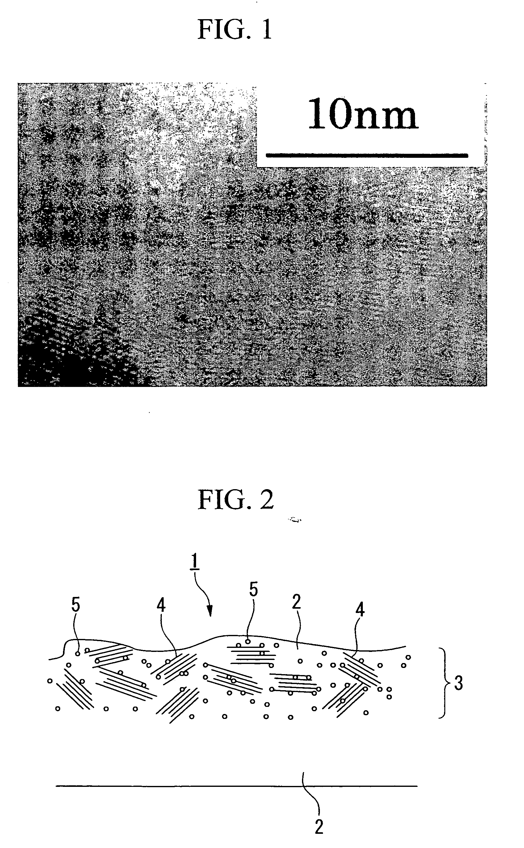
[0090] A silicone rubber that had been vulcanized having a thickness of 15 μm (elastic modulus in shear of 1×10⁷ Pa at normal temperature containing wet silica) was provided as the binding agent on a polyethylene phthalate film used as the support layer having a thickness of 12 μm (elastic modulus in shear of 3.8×10⁹ Pa at the normal temperature), and thereon a composite layer was formed by sputtering Fe—Ni-based soft magnetic metal to an equivalent thickness of 20 nm by physical vapor deposition of the opposing target type magnetron sputtering process, thereby to obtain the electromagnetic noise suppressor. Sputtering was carried out by applying a low negative voltage so as to impart energy of 8 eV to the vaporized particles while maintaining the substrate at the normal temperature.

[0091] Then a thin portion was sliced by means of a microtome from the electromagnetic noise suppressor thus obtained and, after polishing the cut surface by ion beam, cross section of the composite lay...

example 2

[0092] An epoxy resin of B stage having a thickness of 25 μm (elastic modulus in shear of 8×10⁶ Pa before curing and elastic modulus in shear of 2×10⁹ after curing) was provided as the binding agent on a polyethylene terephthalate film that had been subjected to mold-release treatment and used as the support layer having a thickness of 12 μm, and thereon a composite layer was formed by depositing Fe—Ni-based soft magnetic metal to an equivalent thickness of 10 nm by physical vapor deposition of the opposing target type magnetron sputtering process. Sputtering was carried out by applying a low negative voltage so as to impart energy of 8 eV to the vaporized particles while maintaining the substrate at the normal temperature. The epoxy sheet was removed from the polyethylene phthalate film and was cut into halves, and the epoxy sheet were placed on the other so that the composite layers were stacked alternately. The stack was heated to 40° C. for 6 hours then 120° C. for 2 hours so as...

example 3

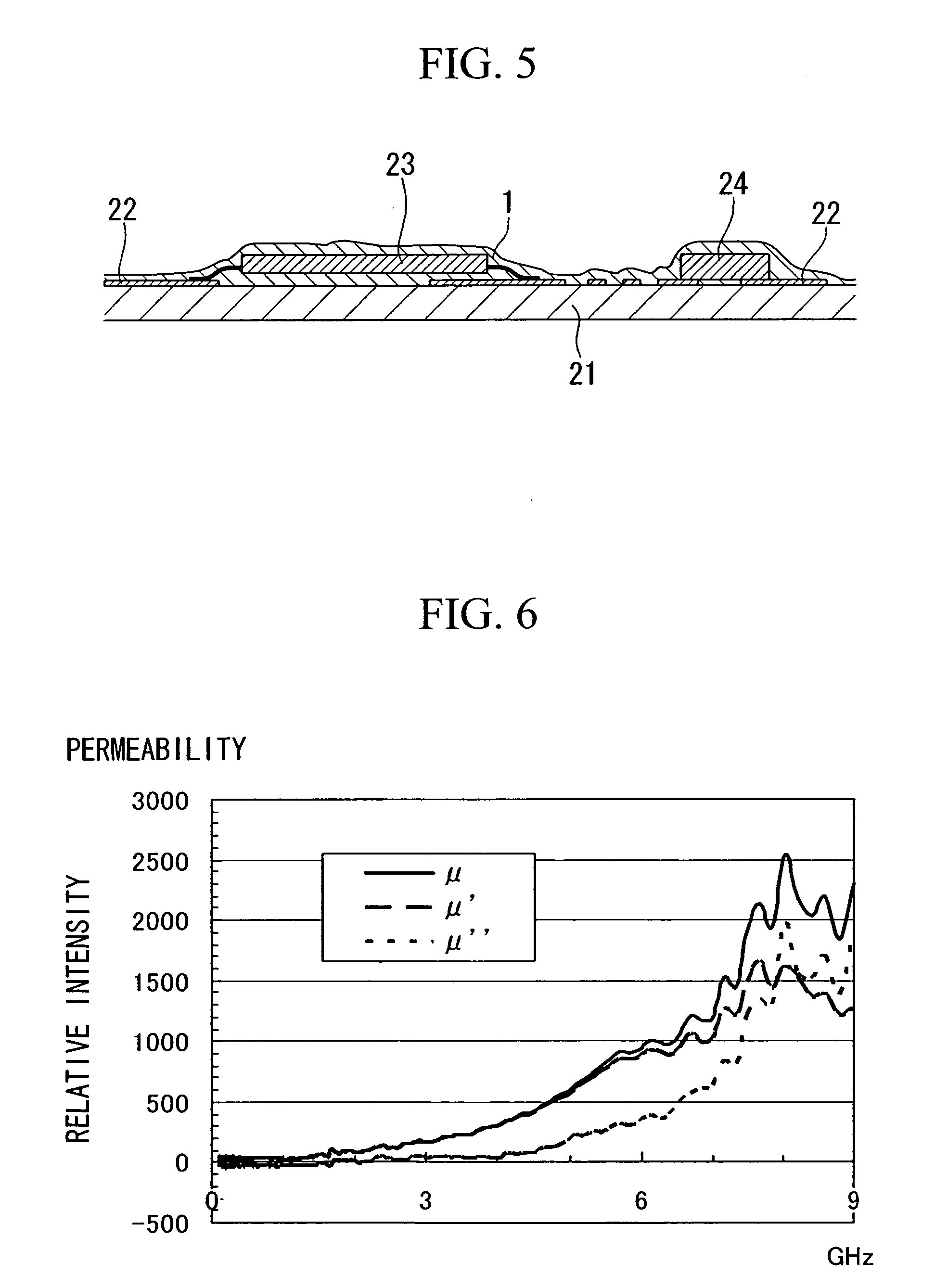
[0093] Metal Ni was deposited to a thickness of 30 nm on one side of a polyimide film used as the support layer having a thickness of 12 μm, and provided on the other side was vulcanized electrically conductive silicone rubber having a thickness of 7 μm (elastic modulus in shear of 2×10⁷ Pa at the normal temperature with 15% by weight of carbon black included) as the binding agent. Then composite layers were formed on the top and bottom surfaces by depositing a Fe—Ni-based soft magnetic metal to equivalent thickness of 20 nm by physical vapor deposition of opposing target type magnetron sputtering process, thereby to obtain an electromagnetic noise suppressor. Sputtering was carried out by applying a low negative voltage so as to impart energy of 8 eV to the vaporized particles while maintaining the substrate at the normal temperature. Relative intensity of μ″L of the imaginary part of the complex magnetic permeability was 180 and relative intensity of μ″H was about six times the va...


PUM

PropertyMeasurementUnit
magnetic resonance frequencyaaaaaaaaaa
resonance frequencyaaaaaaaaaa

Abstract

An electromagnetic noise suppressor of the present invention has magnetic resonance frequency of 8 GHz or higher, and the imaginary part μ″H of complex magnetic permeability at 8 GHz is higher than the imaginary part μ″L of complex magnetic permeability at 5 GHz. Such an electromagnetic noise suppressor is capable of achieving sufficient electromagnetic noise suppressing effect over the entire sub-microwave band. The electromagnetic noise suppressor can be manufactured by forming a composite layer 3 on the surface of a binding agent 2 through physical deposition of a magnetic material on the binding agent 2. The structure with an electromagnetic noise suppressing function of the present invention is a printed wiring board, a semiconductor integrated circuit or the like that is covered with the electromagnetic noise suppressor on at least a part of the surface of the structure.

Description

TECHNICAL FIELD [0001] The present invention relates to an electromagnetic noise suppressor that suppresses electromagnetic noise, to a structure with an electromagnetic noise suppressing function, and to a method of manufacturing the same. BACKGROUND ART [0002] In recent years, as the use of the Internet has increased, electronic apparatuses that use CPUs running at high clock frequencies in a sub-microwave band (0.3 to 10 GHz), electronic apparatuses that use high frequency bus, and telecommunication apparatuses that utilize radio waves have been increasing, such as personal computers, home appliances having information processing functions, wireless LAN, bluetooth-equipped apparatuses, optical module, mobile telephones, mobile information terminals and intelligent road traffic information system. This trend leads to a society of ubiquitous computing that requires devices of higher performance with high-speed digital information processing function and low-voltage driving. However...

Claims


Application Information

Patent Timeline
Patent Type & Authority Applications(United States)
IPC IPC(8): H04B3/28H01F1/00H01F1/28H01F17/04H01F27/36H01F41/20H01L23/552H01L27/146H05K1/02H05K3/28H05K9/00
CPCH01F1/00Y10T428/269H01F17/04H01F27/365H01F41/20H01F2017/065H01L23/552H01L27/14618H01L2924/3011H05K1/0233H05K3/284H05K3/285H05K9/0083H05K9/009H05K2201/083H05K2201/086H01L2924/0002H01F1/28Y10T428/32Y10T428/325H01L2924/00H01F27/36H01F27/366
Inventor KAWAGUCHI, TOSHIYUKITANIGUCHI, ATSUSHIGONDA, TAKASHI
Owner SHIN-ETSU POLYMER CO LTD
Why Eureka
Try Eureka