Electromagnetic fields increase in vitro and in vivo angiogenesis through endothelial release of FGF-2

a technology of endothelial release and angiogenesis, which is applied in magnetotherapy, magnetotherapy using coils/electromagnets, magnetotherapy, etc., can solve the problem that it is unlikely that pemf will achieve clinical success

Inactive Publication Date: 2005-03-03
NEW YORK UNIV +1
View PDF34 Cites 69 Cited by
  • Summary
  • Abstract
  • Description
  • Claims
  • Application Information

AI Technical Summary

Problems solved by technology

Thus, it seems unlikely that the clinical success of PEMF is entirely attributable to an effect on osteoblasts alone.

Method used


Image

  • Electromagnetic fields increase in vitro and in vivo angiogenesis through endothelial release of FGF-2
  • Electromagnetic fields increase in vitro and in vivo angiogenesis through endothelial release of FGF-2
  • Electromagnetic fields increase in vitro and in vivo angiogenesis through endothelial release of FGF-2

Examples


example 1

Cell Culture

[0029] HUVECs (Clonetics, San Diego, Calif.) were cultured in endothelial basal medium (EBM-2) supplemented with EGM-2MV and studied at passages 4-7. Fibroblasts were harvested from newborn foreskin specimens (Freshney, in Culture of Animal Cells: A Manual ofBasic Technique, pgs. 149-175. Wiley-Liss, Inc., New York, 2000, which is hereby incorporated by reference in its entirety). Osteoblasts were harvested from fetal rat calvaria (Steinbrech et al., “VEGF Expression in an Osteoblast-Like Cell Line is Regulated by a Hypoxia Response Mechanism,”Am. J Physiol. Cell. Physiol. 278:C853-60 (2000), which is hereby incorporated by reference in its entirety). Both fibroblasts and osteoblasts were cultured in DMEM supplemented with 10% FBS and 100 μg / ml penicillin G, 50 μg / ml streptomycin and 0.25 μg / ml amphotericin B.

example 2

Exposure to PEMF

[0030] Pulsed electromagnetic fields were generated by a bone healing device (EBI, Parsippany, N.J.) delivering uniform time-varying fields. Fields consisted of asymmetric 4.5 msec pulses repeated at 15 Hz, with a magnetic flux density rising from 0 to 12 gauss in 200 μsec and returning to 0 G in 25 μsec. PEMF generators were placed inside identical incubators, but only turned on in the test incubator. Extraneous 50 Hz magnetic fields within each incubator were less than 2 mG. Custom designed cages surrounded with the same configuration were employed for the in vivo experiments.

example 3

In Vitro Angiogenesis Assay

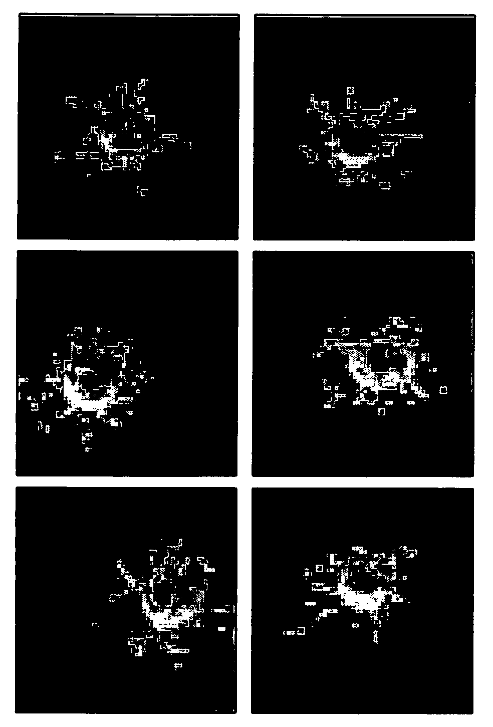
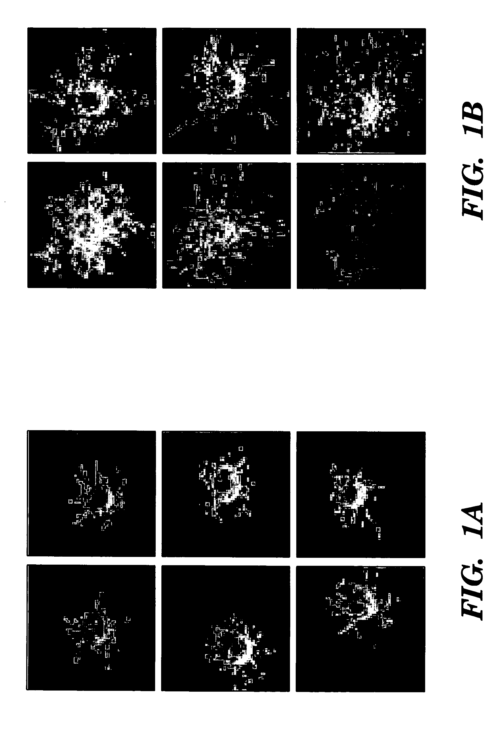
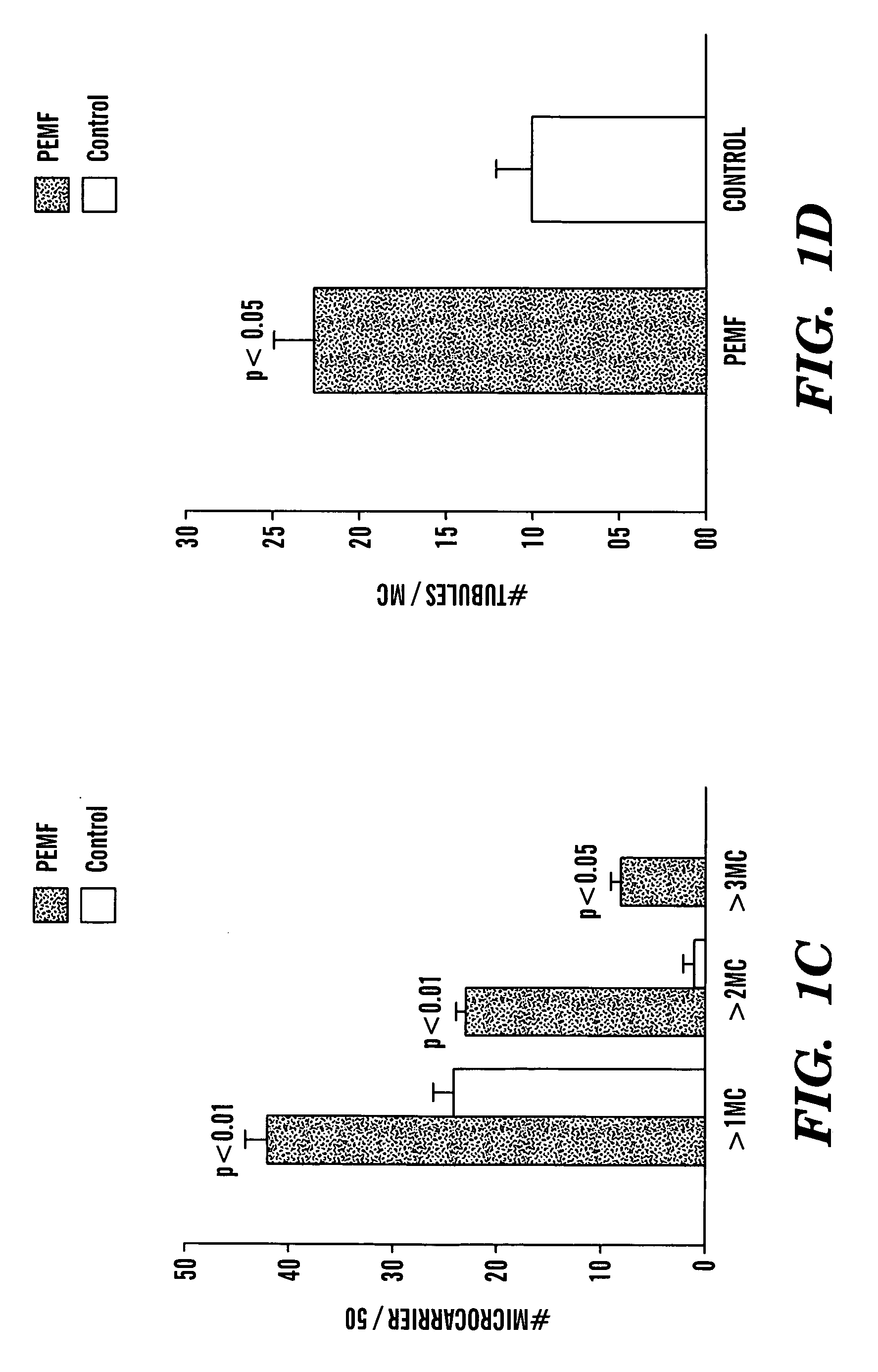
[0031] A microcarrier (“MC”) in vitro angiogenesis assay was performed as previously described (Nehls et al., “A Novel, Microcarrier-Based In Vitro Assay for Rapid and Reliable Quantification of Three-Dimensional Cell Migration and Angiogenesis,”Microvasc. Res. 50:311-322 (1995), which is hereby incorporated by reference in its entirety). HUVECs were added to a suspension of MCs (Cytodex 3®), and cultured until confluent. Fibrin gels were prepared by dissolving fibrinogen (Sigma, St. Louis, Mo.) in PBS (2.5 mg / ml) along with 200 U / ml of aprotinin to prevent excessive fibrinolysis. Confluent HUVEC-seeded MCs were added to each well and polymerization was achieved at 1 hour by adding thrombin (0.625 U / ml). Gels were cultured in the presence or absence of PEMF for 7-10 days. The degree of angiogenesis was quantified by two blinded observers assessing 50 MCs at random and counting: (1) the number of MCs with tubules greater than one, two, or three MC diameter...


PUM


Abstract

The present invention relates to a method of inducing angiogenesis in a cell or tissue by applying an electromagnetic field to the cell or tissue under conditions effective to induce angiogenesis. Also disclosed is a method of treating an ischemic condition in a patient by applying an electromagnetic field to ischemic tissue in a patient under conditions effective to treat the ischemic condition by inducing angiogenesis. A method of tissue engineering is also disclosed. This method involves providing a tissue scaffold and subjecting the tissue scaffold to an electromagnetic field under conditions effective to form a vascularized tissue scaffold. Further disclosed is a method of inducing activity of angiogenic growth factors by applying an electromagnetic field to a cell or tissue under conditions effective to induce activity of an angiogenic growth factor.

Description

[0001] This application claims the benefit of U.S. Provisional Patent Application Ser. No. 60 / 469,711, filed May 12, 2003, which is hereby incorporated by reference in its entirety.FIELD OF THE INVENTION [0002] This invention relates to methods of inducing angiogenesis, treating an ischemic condition, tissue engineering, and inducing activity of angiogenic factors by application of electromagnetic fields. BACKGROUND OF THE INVENTION [0003] Electromagnetic forces are believed to play a role in the normal repair of human tissues. The therapeutic efficacy of various forms of electrical stimulation, including capacitative coupling, direct current, combined magnetic fields, and pulsed electromagnetic fields (“PEMF”) have been intensely investigated over the past 30 years (Bassett et al., “Augmentation of Bone Repair by Inductively Coupled Electromagnetic Fields,”Science 184:575-577 (1974); Ryaby, “Clinical Effects of Electromagnetic and Electric Fields on Fracture Healing,”Clin. Orthop. ...

Claims


Application Information

Patent Timeline
Patent Type & Authority Applications(United States)
IPC IPC(8): A61N2/00A61N2/02A61N2/04
CPCA61N2/02A61N2/00
Inventor GURTNER, GEOFFREY C.TEPPER, ORENLEVINE, JAMIE
Owner NEW YORK UNIV
Why Eureka
Try Eureka