Small electron gun

a small electron gun and electron gun technology, applied in the field of electron gun, can solve the problems of inability to substantially keep a high vacuum pressure, limit in downsizing the ion pump, and difficulty in downsizing the ion pump, and achieve the effect of high vacuum pressur

Inactive Publication Date: 2005-03-10
HITACHI HIGH-TECH CORP
View PDF3 Cites 19 Cited by
  • Summary
  • Abstract
  • Description
  • Claims
  • Application Information

AI Technical Summary

Benefits of technology

[0016] By using the present invention, it is possible to obtain an electron microscope or an electron-beam drawing apparatus capable of keeping a high vacuum pressure of approximately 10−10 Torr without using an ion pump.

Problems solved by technology

However, with conventional methods, it is difficult to downsize an ion pump because the pump has a large size and a magnetic field leaks and it is necessary to set the ion pump by keeping a certain distance from an electron gun as shown in FIG. 2.
However, because the diameter of the ion pump housing is at least approximately tens of centimeters, there is a limit in downsizing the ion pump.
However, when using the nonevaporative getter pump, it is difficult to exhaust a rare gas such as helium or argon and a chemically stable gas such as methane, it is impossible to substantially keep a high vacuum pressure, and thus the pump is not practically used yet.
However, when using a chemically stable gas such as a rare gas or fluorocarbon gas, it is difficult to exhaust the gas because it is completely equilibrium.

Method used


Image

  • Small electron gun
  • Small electron gun
  • Small electron gun

Examples


first embodiment

[0033] First Embodiment

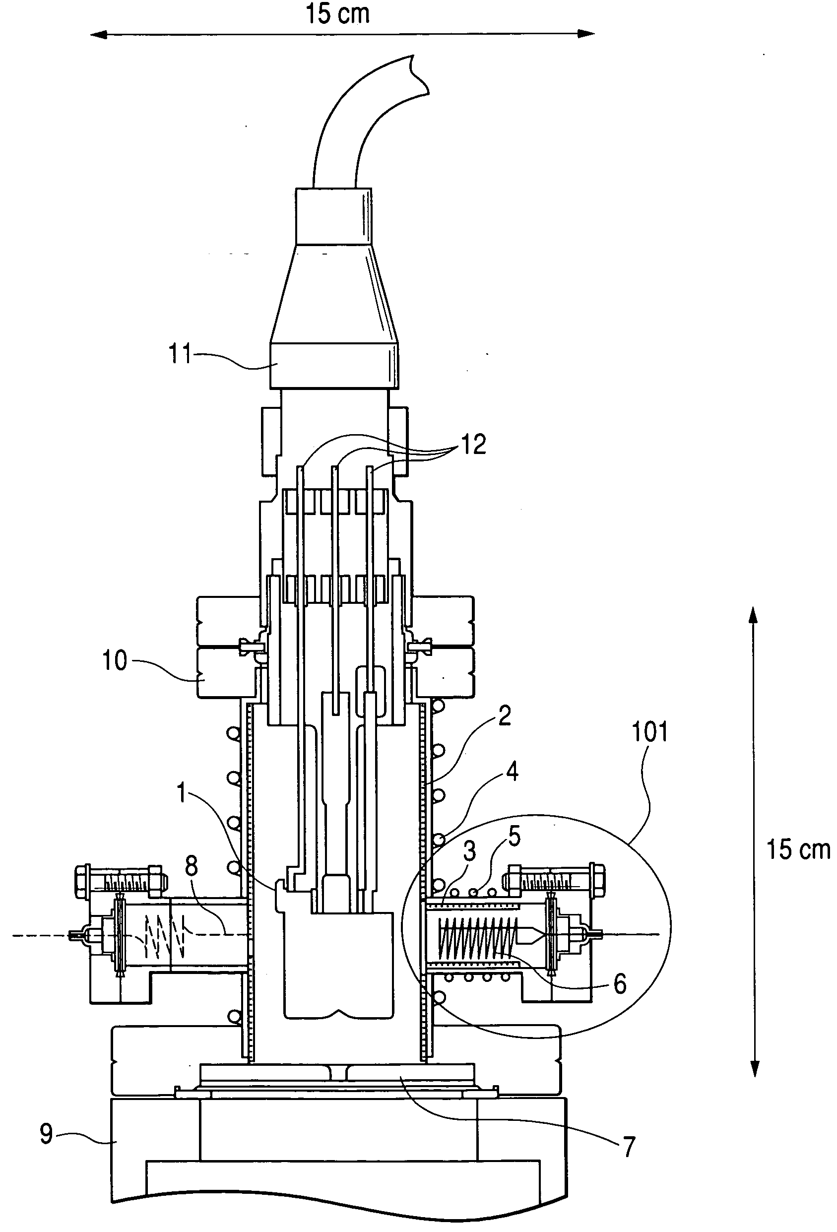
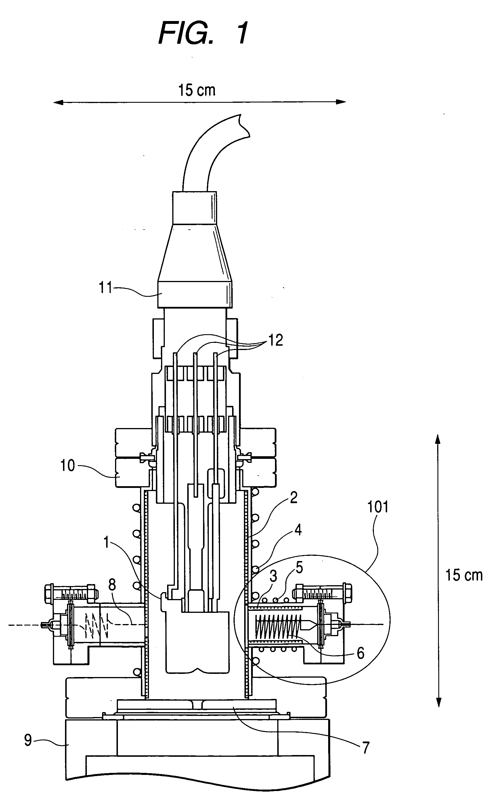
[0034]FIG. 1 shows a configuration of an electron gun of this embodiment. An electron source uses a thermal-field-emission electron gun (TFE) 1. The electron source 1 is set to the flange of an ICF 70 [WHAT IS “ICF 70”→It's a standard of flange used in a vacuum industry] and connected with an introduction terminal 12 to an electrode (suppressor, drawer, or chip) (not shown). The electron source 1 is inserted into and fixed to an electron-gun column 10.

[0035] The inside diameter of this column is approximately 37 mm. The column 10 has a sheeted nonevaporative getter pump 2 along the inside diameter. The nonevaporative getter pump 2 is activated when overheated to take in air. Therefore, a first heater 4 is set to the outside of the electron-gun column 10. This embodiment uses the heater 4 by winding a sheath heater on the electron-gun column 10. Note that a nonevaporative getter-pump heating device may be set in the vacuum vessel, in other words, the electron-...

second embodiment

[0044] Second Embodiment

[0045] This embodiment describes the electron gun, described in the first embodiment, as applied to a scanning electron microscope.

[0046]FIG. 3 shows a schematic configuration of the scanning electron microscope of this embodiment. From the viewpoint of being advantageous for downsizing, every electronic optical system used in this embodiment uses a small electronic optical system constituted by an electrostatic lens. In FIG. 3, an electron beam 18 field-emitted from a field-emission electron gun 17 is thinly converged by electric fields formed between electrodes of an electrostatic lens set below the electron gun 17 and applied onto a sample 25. The electrostatic lens comprises a third lens electrode 19, a second lens electrode 20, and a first lens electrode 21.

[0047] At the same time, the electron beam 18 is deflected in the internal space of the second lens electrode 20 by a deflector 24 to two-dimensionally scan the surface of the sample 25. Moreover, t...

third embodiment

[0053] Third Embodiment

[0054] This embodiment describes the electron gun, described in the first embodiment, as applied to an electron-beam drawing apparatus. To provide a pattern drawing function for the small scanning electron microscope described in the second embodiment, the microscope may be used as an electron-beam drawing apparatus.

[0055]FIG. 4 is a schematic diagram of an electron-beam drawing apparatus of the third embodiment. It is possible to draw a pattern having a resolution of 6 nm on a resist film applied onto a sample 31 by sequentially reading data from a pattern record control device 30, previously storing the data for the layout of a pattern and the like, and deflecting an electron beam 18 by a deflector 24 so as to form the pattern. Moreover, it is possible to detect the position of a pattern to be drawn by detecting a secondary electron beam 33 generated from a region nearby a positioning mark, not shown, by a secondary electron detector 26. Because this embodi...


PUM


Abstract

To provide a small electron gun capable of keeping a high vacuum pressure used for an electron microscope and an electron-beam drawing apparatus. An electron gun constituted by a nonevaporative getter pump, a heater, a filament, and an electron-source positioning mechanism is provided with an opening for rough exhausting and its automatically opening/closing valve, and means for ionizing and decomposing an inert gas or a compound gas for the nonevaporative getter pump. It is possible to keep a high vacuum pressure of 10−10 Torr without requiring an ion pump by using a small electron gun having a height and a width of approximately 15 cm while emitting electrons from the electron gun.

Description

CLAIM OF PRIORITY [0001] The present invention claims priority from Japanese application JP 2003-317703 filed on Sep. 10, 2003, and JP 2004-111682 filed on Apr. 6, 2004, the content of which is hereby incorporated by reference in its entirety. BACKGROUND OF THE INVENTION [0002] 1. Field of the Invention [0003] The present invention relates to an electron gun of an electron microscope or electronic drawing apparatus, particularly to downsizing of an electron gun. [0004] 2. Discussion of Background [0005] A conventional scanning electron microscope (SEM) or electron-beam drawing apparatus (EB) accelerates an electron beam emitted from an electron gun constituted by a field-emission or thermal-field-emission electron source, forms the electron beam into a thin electron beam by an electron lens, forms the thin electron beam into a primary electron beam, thereby scans the surface of a sample with the primary electron beam by an electronic deflector to obtain an image by detecting obtaine...

Claims


Application Information

Patent Timeline
Patent Type & Authority Applications(United States)
IPC IPC(8): H01J37/18H01J7/16H01J7/18H01J37/07H01J37/073H01J41/20
CPCH01J7/16H01J7/18H01J37/07H01J37/18H01J2237/188H01J2237/062H01J2237/06316H01J2237/1825H01J2237/022
Inventor KATAGIRI, SOICHIOHSHIMA, TAKASHI
Owner HITACHI HIGH-TECH CORP
Why Eureka
Try Eureka